29
4-10 Assembling the rear case
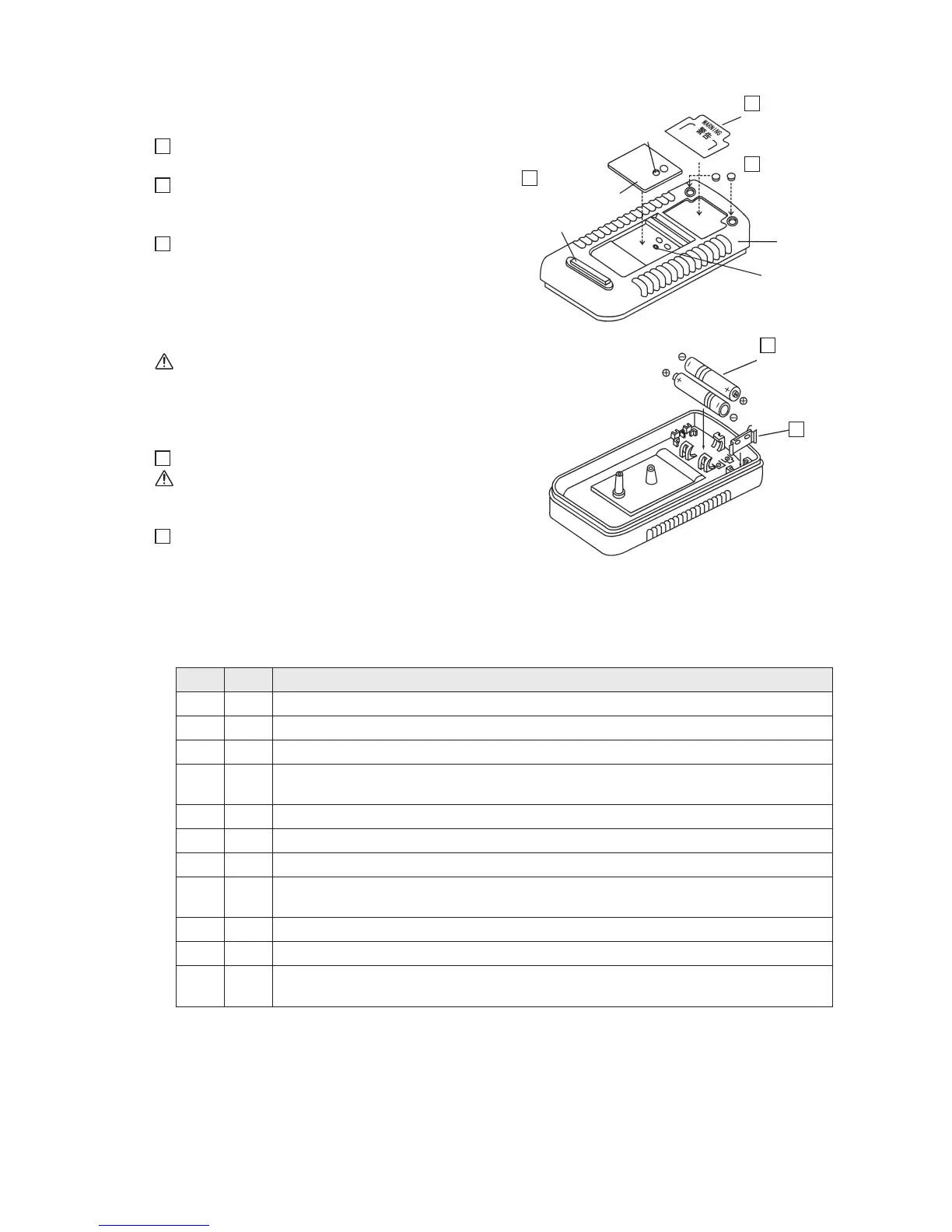
Fig. 4-16
14
Attach the warning label after removing its
backing sheet.
15
Remove the round rubber foots from the
mounting paper board and firmly set them (2
places).
16
As shown in Fig. 4-18, open the stand (the
figure is omitted). Attach the dial A
(semitranslucent, purple-colored) to the rear
case after removing the backing sheet (white)
on its bottom side.
Remove the protective film on the surface side.
Caution:
Align the through-screw-hole in the dial A
with the female threads in the rear case.
Fig. 4-17
17
Attach the battery terminals.
Caution:
The rounded side of each battery terminal
should come to the top.
18
Place the dry cells with their polarities
matching those engraved on the rear case.
4-11 Assembling and operation checks
1. Checks before assembling the panel with the rear case (1 through 11)
Fig. 4-16
Fig. 4-17
Rectangular
rubber foot
2. Assembling the panel with the rear case and subsequent work: (1) through (3)
(1) Turn OFF the Function switch.
(2) Completely assemble the panel with the rear case by engaging the concavity (slot) with the
convexity at their respective leading ends at an angle of about 20 degrees (left side in Fig. 4-18).
(3) Open the stand and secure the rear case to the panel by using a screw of M3 x 22 (right side
in Fig. 4-18).
16
Dial A
(semitranslucent,
purple-colored)
Warning label
(remove backing
paper)
Battery terminal
Dry cell
Rounded
side
Round rubber foot
Rear case
Female thread
14
18
17
15
Through-
screw-hole
Check
Order Description
1 Check that the printed circuit board is snapped in below 7 pawls on the panel.
2 Check that the dial is properly attached to the panel.
3 Check that all of the resistors and the spark gaps are soldered.
4
Check that the connector covers do not significantly deviate from their
corresponding holes in the panel.
5 Check that the fuse is in place.
6 Check that the battery terminals are upright before placing dry cells.
7 Check that the polarities of the buzzer are correct.
8
Check that the wiring lead wires are not routed above any mounting hole for the
rear case or the Function switch.
9 Check that the Function switch smoothly turns (1/3 turn).
10 Check that the safety cover smoothly rotates (1/3 turn).
11
Check that the rubber switch returns to the original position after it has been
pressed with your finger and then released.