28
①
③
②
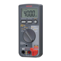
Fig. 4-12
4
Mount the zebra-striped connector onto the
stepped part of the LCD that is fit into the
panel.
Caution:
During work, ensure that no foreign matter
attaches to the conductive surface.
5
Mount the rubber switch onto the panel.
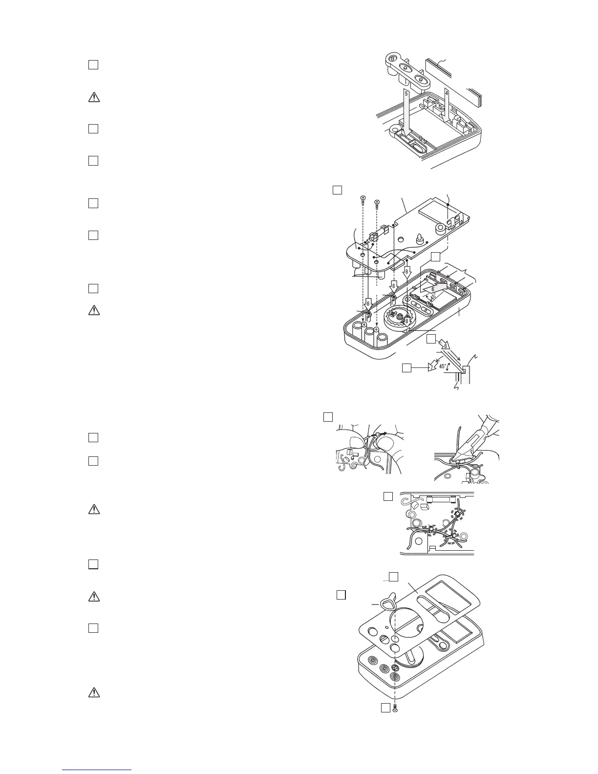
Fig. 4-13
6
Fully insert the leading end of the printed
circuit board (large) at an angle of about 45
degrees into the area surrounded by four
circuit-board securing pawls on the panel.
7
Press the printed circuit board (large) down to
the panel while strongly pressing it toward its
leading end.
8
Align three notches of the printed circuit board
(large) with three pawls of the panel and then
snap the printed circuit board into the panel
(ensure that the three notches have properly
engaged with the lower parts of the pawls).
9
Attach the printed circuit board (small) to the
panel by using screws of M3 x 8.
Caution:
• Tighten the screws while adjusting the
position of the printed circuit board
(small) so that three connector covers do
not deviate from the centers of their
corresponding holes in the panel as
viewed from the surface side of the panel.
• Particularly note that excessively
tightening the screws would damage their
threads.
Fig. 4-14
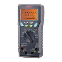
10
After attaching circuit board to the front case,
fasten 3 points of the cables.
11
Fasten 3 points of the cables.
(
①
V, B and COM cable,
②
V and W,
③
B,
COM and W)
*Refer page 26
Caution:
Bindcablesascloseaspossibletotheirroots,
andcutextras.
Fig. 4-15
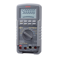
12
Remove the backing sheet on the bottom of
the dial and then attach the dial to the
concavity in the panel.
Caution:
Before attaching the dial, check that the
LCD surface is free from foreign matter.
13
Pass the safety cover through the spring arm
attached to the panel and then secure it with a
screw of M2 x 8 from the reverse side. Once
completely tighten the screw and then loose it
by about a half turn to check that the safety
cover rotates properly.
Caution:
If the safety cover fails to return to the
original position with the spring force,
loosen the screw by another half turn.
Fig. 4-12
Fig. 4-13
Fig. 4-14
Fig. 4-15
9
6
6
7
13
Zebra-striped
connector
Pawl for
securing the
printed circuit
board on panel
Conductive surface
(same as on the
opposite side)
Rubber switch
Zebra-striped connector
Pawl
Press
Engage
Pawl
Pawl
Printed circuit
board (large)
Connector
cover
Printed circuit
board (large)
Screw of 3 x 8
Leading end of printed
circuit board (large)
Printed circuit
board (small)
Pawl for securing
the printed circuit
board
Safety cover
Dial
Screw of 2 x 8
12
13
11
10
Front case