30
Caution:
If any of the display elements, which should be illuminated on the LCD in order 1, is missing, it is
attributable to a contact failure due to foreign matter included somewhere between the LCD, the
zebra-striped connector and the printed circuit board (large). Perform the steps in 4-9 again (page 27).
4-12 Adjustments
1. Adjustment environment
Choose an indoor location where temperature is
18-28 °C and relative humidity 75 % maximum
without exposure to direct sunlight.
2. Order of adjustments
The PC20TK is designed to show any of the readings
within the accuracy shown in "2-3 Specification" after
the DCV adjustment has been completed.
(1) Set the Function switch to
/
.
(2) Apply 3.8 VDC output from the voltage generator
between the negative (COM) and positive connectors of the PC20TK.
(3) Vertically insert the insulated screwdriver (*) for adjustment use through the DCV adjustment
hole (DCV • ADJ) in the panel surface and fit it into the slot in the pre-set resistor located
inside. Slowly turn the screwdriver clockwise or counterclockwise so that the reading falls
within the range of 3.799-3.801 V. Turning the screwdriver counterclockwise will decrease the
reading, while turning it clockwise will increase the reading.
* Applicable blade of screwdriver: 2.3 in width x 0.4-0.5 mm in thickness; shaft: 4.2 mm
max. in diameter and 15 mm min. in length
(4)
After the adjustment, close the adjustment hole with the oval seal (one seal is provided for spare use).
If a standard voltage generator with high accuracy is not available, make connections
as shown in (1) in Fig. 5-1 and then make an adjustment by matching the reading on the
PC20TK with that of the voltmeter used as standard.
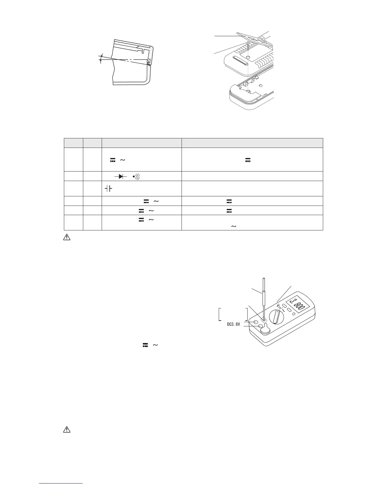
Fig. 4-18:
Assembling the panel with the rear case
Mounting
screw M3 x 22
for rear case
Stand
3. Checking the readout (1 through 6)
Once the reading is assembled properly, it functions as shown in the right column in accordance
with the respective position of the Function switch.
Panel
About 20 ˚
Rear case
Check
Order
Position of Function switch
Function
1V
/
All the display elements are illuminated (see Fig. 1-3)
and then AUTO RS232C xxx.x mV is displayed (xxx.x
is not constant; it always varies)
2
Ω /
/
AUTO RS232C O.L MΩ is displayed.
3
AUTO RS232C xx.xx nF is displayed (xx.xx is not constant;
it is a value approximately within the range of 00.10-00.35)
4 400
•
4000 µA / AUTO RS232C 000.0 µA is displayed.
5 40
•
400 mA / AUTO RS232C 00.00 mA is displayed.
6
40
•
400 mA /
(Press the SELECT switch once.)
• The buzzer sounds.
• AUTO RS232C
00.00 mA is displayed.
Fig. 4-19:
DCV adjustment
Screwdriver for
adjustment use
DCV Function
Adjustment hole
(DCV ADJ)
After the adjustment,
close the adjustment
hole with the oval seal.