5
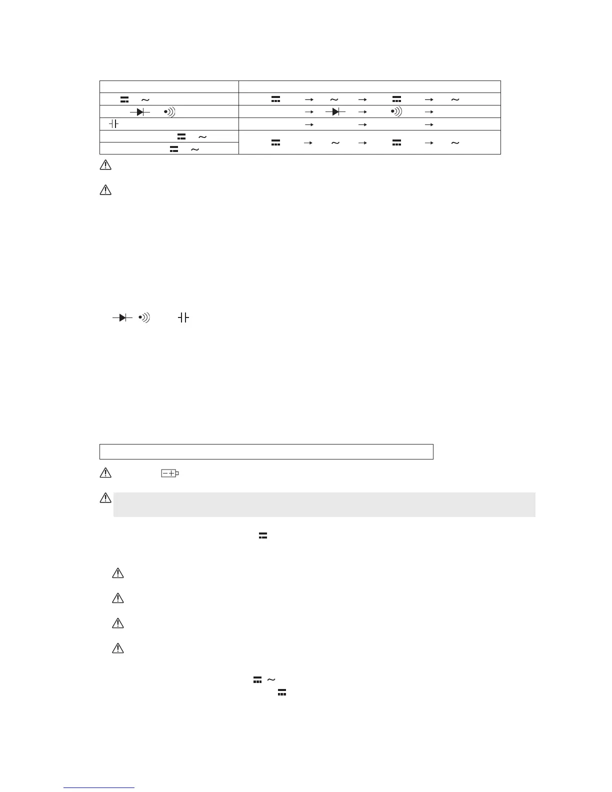
9. Select switch
Pressing this switch toggles the functional modes in the following order:
Immediately after the Function switch has been changed, the leftmost functional mode in the
right column of the above table is selected in the auto mode.
The PC20TK provides no automatic power-off capability. After finishing measurement, be
sure to turn OFF the Function switch.
2-5 Preparations for measurement
Connecting the test leads
Connect the black plug of the test lead to the COM (-) connector. Change the connection of the red
plug in accordance with the functional mode to be used, as follows:
To measure current, fully connect the red plug into the µA & mA measurement connector. To make
measurements for voltage, resistance, a diode check, and others, fully connect the plug into the V,
Ω,
, , and (+) measurement connector, respectively.
2-6 Measuring procedure
When the Function switch is set to a desired functional mode, the power switch is turned ON and
the reading and others are displayed on the readout.
Immediately after the switch has been changed, any selected functional mode becomes active in
the auto mode (with the AUTO mark displayed on the upper left part of the readout). "RS232C" is
also displayed for any functional mode. This indicates that the measured values are output as
digital signals through the LED located on the rear of the PC20TK (see 9 on page 10).
The following explanation is made assuming that the auto mode is active:
When the mark appears on the upper right part of the readout, the built-in batteries have
run out. Replace the batteries.
Be sure to turn OFF the Function switch after finishing measurement. The batteries would
otherwise be consumed.
1. Measuring DC voltage - DCV (V
) (see Fig. 2-1)
This functional mode is used to measure the voltage of a battery, that in a DC circuit of a device,
or other voltage.
Warning: Be sure to measure voltage in parallel with the object under measurement (e.g.,
power source).
Warning: The O.L. mark does not appear even if overvoltage of 750 V or more is applied to
the input connector.
If voltage with reversed polarities is applied to the measurement connectors, the negative (-)
signal is displayed with the reading.
In the auto mode, the reading fluctuates when the test leads are released, but this is not a
malfunction.
(1) Set the Function switch to V
/
.
(2) Press the Select switch to display
on the upper left part of the readout.
(3) Make the test pins contact with the object under measurement and then read the value
displayed.
V
/
Ω
/
/
400 / 4000 µA /
40 / 400 mA /
Functional mode Toggling order
Ω
Ω
(Without symbol)
REL
(Without symbol)
REL