33
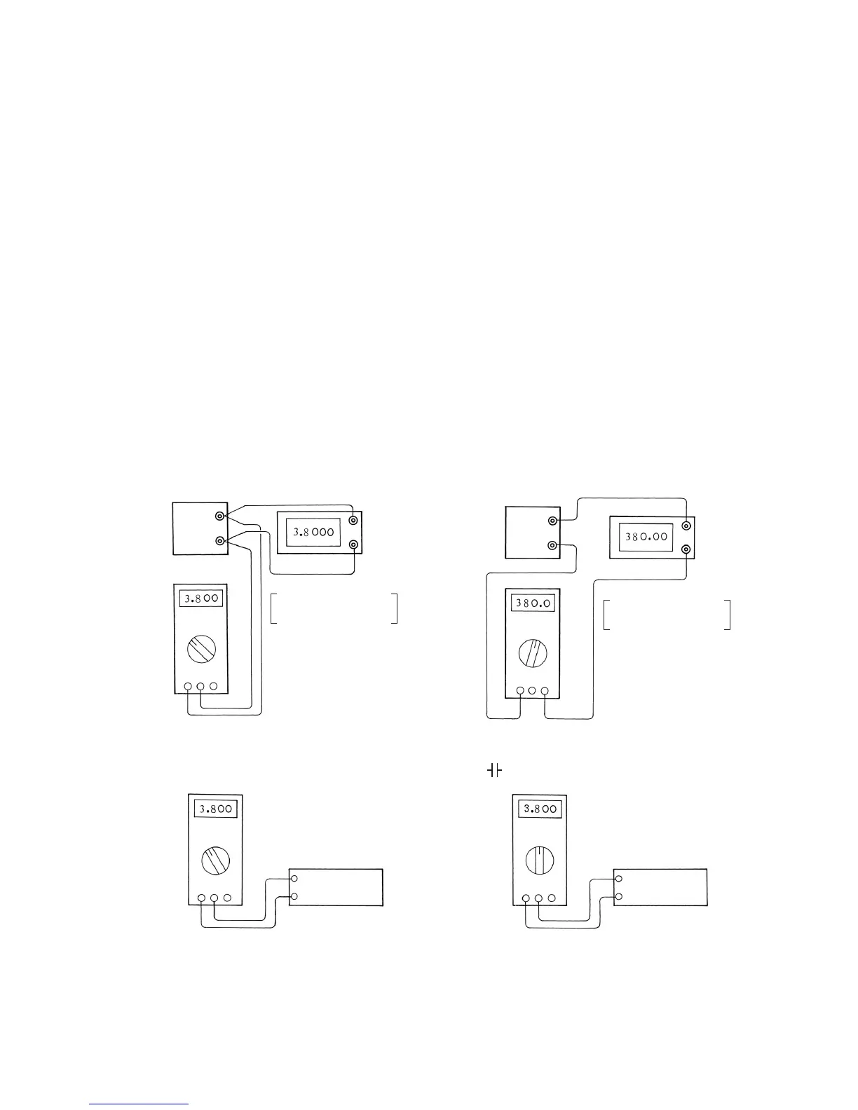
Fig. 5-1: Connections for calibration
[5] Inspection and Calibration
After the adjustments have been finished, inspect readings in each functional mode as the final stage.
Based on this result, calculate error rates and accuracy, and complete "5-3 Table for test results."
Obtain error rates using the equation given in "5-2 Error rate." To determine the accuracy range,
perform calculations by the procedures described in "2-3 Specification" and "4 Accuracy" under "2-4
Explanation of function." If the reading on the PC20TK markedly deviates from the corresponding
standard input, the possible causes include a missing component and a short-circuit due to
overhanging solder in the patterns on the printed circuit boards. An error that slightly deviates from
the accuracy range shown in "2-3 Specification" is attributable to a deviation as described in "4-12
Adjustments." In rare cases, the error of a circuit component is too large.
5-1 Calibration procedure
The PC20TK is typically calibrated by making connections as shown in Fig. 5-1, matching the
reading of the unit (this multitester) under test with the target value while changing the output from
the generator, and then reading the value displayed on the generator (or reading the value
displayed on the PC20TK against the standard input). Enter the calibration result as in the example
of completing the table for test results on page 34. Use the test result form on page 37 or its
photocopy.
1. DCV, ACV
2. DCµA • mA, ACµA • mA
3. Ω
4.
Multimeter under
measurement
Multimeter under
measurement
Multimeter under
measurement
Multimeter under
measurement
Variable
voltage
generator
Variable standard
resistor
Variable standard
capacitor
Variable
current
generator
Standard
digital voltmeter with
4-1/2 digits minimum
Standard
digital ammeter with
4-1/2 digits minimum