14
3-4 Working of input signal conversion section
The following typical example is assumed to explain how each input signal is processed to obtain
DC voltage that will be applied to the A/D conversion section.
1. DC voltage (DCV)
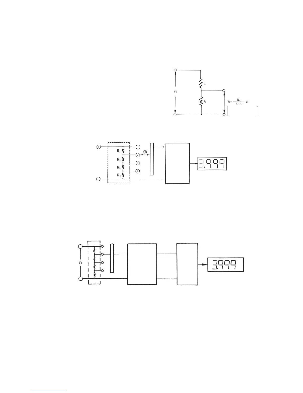
For measurements of DV voltage, the user selects
the most suitable range in accordance with the
voltage level to be measured. A voltage divider is
used to provide different ranges and this circuit is
also known as an attenuator. As shown in Figs.
3-4 and 3-5, resistors are connected in series to
divide input voltage Vi into smaller voltage using
the resistors. SW stands for a selector switch that
is used to select the most suitable range.
Fig. 3-5: Measuring circuit for DC voltage (DCV)
2. AC voltage (ACV)
For measurements of AC voltage, the input voltage is divided with the voltage divider as shown
in Fig. 3-6 and then AC voltage (ACV) is converted into DC voltage (DCV) with a rectification
circuit.
Fig. 3-6: Measuring circuit for AC voltage (ACV)
3. DC current (DCA) and AC current (ACA)
When current flows through a resistor, voltage drop occurs in proportion to that current. This
means that current has been converted into voltage (current/voltage conversion). For
measurements of current, such voltage is used. Fig. 3-7 shows an example of a DC current
measuring circuit, which uses several resistors of accurate values (electric shunt) so as to enable
the user to select the most suitable range in accordance with the current to be measured. For
measurements of AC current, a rectification circuit is added following the electric shunt, to
convert AC voltage into DC voltage.
Fig. 3-4: Dividing voltage with resistors
The output voltage is
divided according to the
ratio of resistors.
(Input)
DC voltage
(DCV)
(Input)
AC voltage
(ACV)
Voltage divider
Voltage divider
A/D
conversion
section
A/D
conversion
section
AC/DC
conversion
(rectification circuit)
Readout
Readout