16
• Comparator (0-detector)
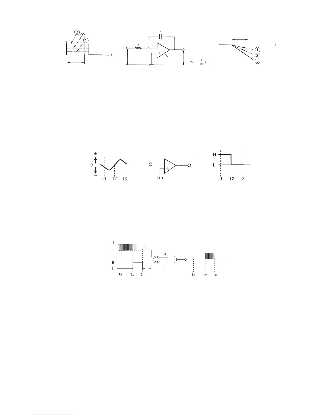
The comparator has an inverting input terminal (negative) and a non-inverting input terminal
(positive). If the former has higher electric potential than the latter, the output decreases nearly
to negative electric potential of the power source (L). In the opposite case, the output
decreases nearly to positive electric potential of the power source (H). In the case shown in Fig.
3-11, the non-inverting input terminal (positive) is at 0 electric potential (grounded). Therefore,
when the inverting input terminal (negative) has positive electric potential (voltage), even if only
slightly, the output becomes L. When the inverting input terminal has negative electric
potential, the output becomes H.
T1
t 1
t 2
T1
t 1 t 2
Fig. 3-10: Integration circuit
Fig. 3-11: Comparator
• AND gate
When a digital signal H (high electric potential) is simultaneously applied to two input terminals
a and b, the output becomes H. If either of the two input terminals is H and the other input
terminal is L or if both terminals are L, then the output becomes L.
Fig. 3-12: AND gate circuit
• Control circuit
This circuit consists of a logic circuit and outputs various kinds of control signals in response to
input signals.
• Counter
This is a digital counter that measures the number of pulses (clock pulses) that have been
received at accurate frequency from the pulse generator.
• Readout
For a digital multimeter, a LCD readout is used to enable efficient reading of the measured
value.
Input voltage
Vi
Input
voltage
Vi
Output voltage Vo
The slope of the line for Vo
becomes larger as Vi increases.
Output voltage
Vo
OP
amplifier
Input
Vi
Input
Output
Vo
Output