17
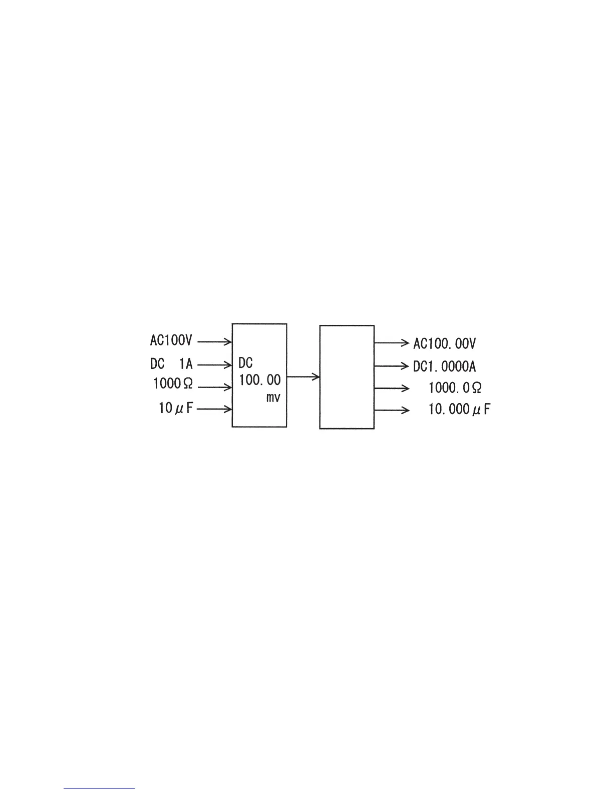
Fig. 3-13: Signal changes
2. Principle of double integration circuit
Vi : Input voltage under measurement
T
1 : Integration period (constant)
Vref : Reference voltage (constant)
T
2 : Reverse integration period
Given the above conditions, the output voltage of the integration circuit is 0 V at the end point of
reverse integration (point t
3 in Fig. 3-15). Hence,
1 1
—
• Vi • T 1 +
—
• ( − Vref ) • T 2 = 0
CR CR
When this equation is transformed into:
T
2
Vi =
—
• Vref
T 1
Vref and T1 are constants with known values.
This means that when T
2 is found, Vi can be calculated.
T
2 is measured as a pulse number by the counter by converting it into the pulse number.
Since T
2 has a proportional relationship with Vi, it is finally displayed as the measured input.
This concept may be simplified, for example, as shown in the following Fig. 3-13:
10,000
signals