25
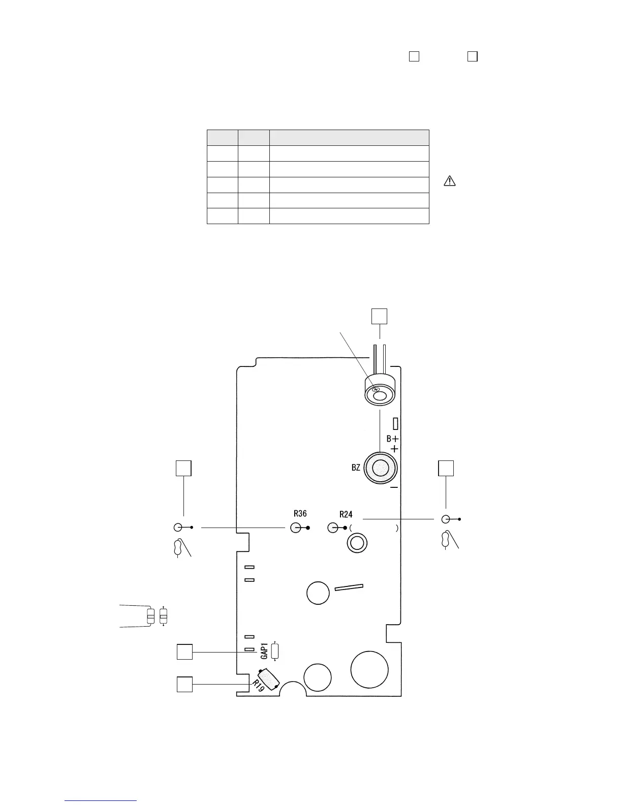
4 BZ : Buzzer
5 R24 : Resistor: 1 Ω
6 R36 :
Resistor: 10 MΩ (with lead wire)
7 GAP1 : Spark gap
8 R19 : Thermistor (PTC)
Check
Order Name of component
2. Mounting components on silk-screen printed surface (part 1):
4
through
8
• Insert the lead wires of each component into the specified holes in the printed circuit board
and then solder them on the opposite mounted surface.
• Be sure to check the polarities of the buzzer.
No components other than the buzzer have polarities.
Fig. 4-7: (Part 1)
After soldering, cut
off the protruding
lead wire with a
nipper.
4
BZ : Buzzer
Be careful about
polarities (mark
on positive side)
5
R24 : 1 Ω
R19 :
Thermistor
7
8
6
R36 : 10 MΩ
Spark gap
(Irrelevant of polarity)
D4 mounted
GAP1 :