26
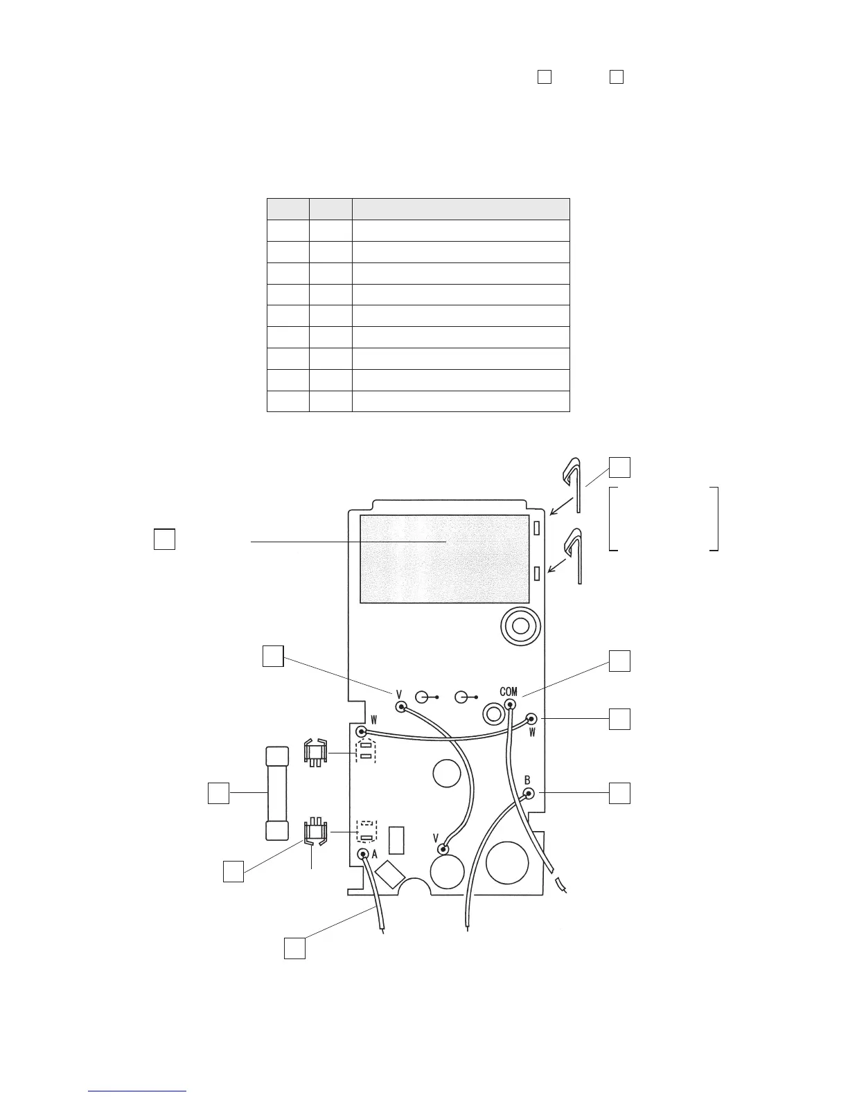
3. Mounting components to silk-screen printed surface (part 2):
9
through
17
• Solder the battery terminals, the fuse folders and the lead wire on the opposite side.
• Insert the two fuse folders into the printed circuit board with attention to their polarities (the
stoppers are positioned mutually outward).
• To solder the fuse folders, previously insert them into the circuit board and attach the fuse to
them. This will facilitate your soldering work.
Fig. 4-8: (Part 2)
Battery pad
(sponge of 55 x 30 mm)
Remove the backing
sheet and then attach
the pad.
COM : Lead wire:
red, 85 mm
Battery terminal
W : Lead wire:
black, 70 mm
B : Lead wire:
black, 70 mm
V : Lead wire: black, 70 mm
F : Fuse
Fuse folder
[Stopper]
A : Lead wire: red, 43 mm
9 Battery terminal (2 pieces)
10 Fuse folder (2 pieces)
11 F : Fuse: 0.5 A/250 V
12 V : Lead wire: black, 70 mm
13 W : Lead wire: black, 70 mm
14 B : Lead wire: black, 70 mm
15 A : Lead wire: red, 43 mm
16 COM : Lead wire: red, 85 mm
17 Battery pad
Check
Order Name of component
12
11
10
15
14
13
16
9
17
stand it vertically
against the circuit
board and then
solder it.