22
2. Example of identifying capacitors (some capacitors have no identification)
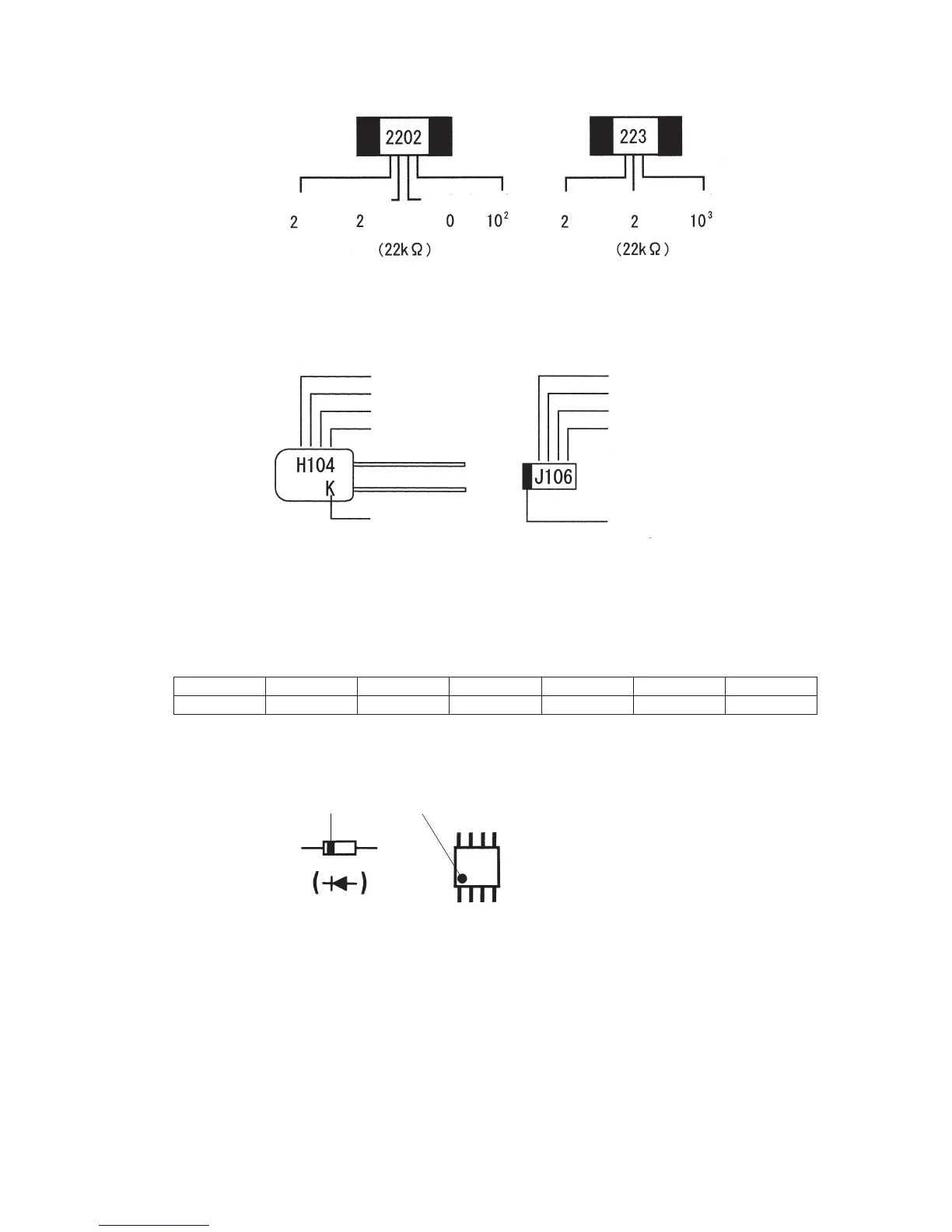
Fig. 4-3(b): Example of identifying resistors
[Example of identifying square chips: 22 kΩ]
1×10
(1+4)
p F = 1×10
5
p F
0.1 µF (50 V) ±10 %
1×10
(1+6)
p F = 1×10
7
p F
10 µF (6.3 V)
Fig. 4-4: Example of identifying capacitors
* Symbols showing rated voltage
Symbol G J A C D H
Rated voltage
4 V 6.3 V 10 V 16 V 20 V 50 V
3. Identifying other components
Fig. 4-5:
Example of identifying
other components
4. Units
Auxiliary units used for capacitors 1 F = 10
6
µF = 1000000 µF
1 µF = 10
3
nF = 1000 nF
1 nF = 10
3
pF = 1000 pF
Auxiliary units used for resistors 1 MΩ = 10
3
kΩ = 1000 kΩ
1 kΩ = 1000 Ω
1 mΩ = 10
-
3
Ω = 0.001 Ω
(Cathode mark)
Diode
(Mark showing the 1st pin)
I C
1st numeral
Rated voltage symbol
1st numeral
2nd numeral
Multiplier
Tolerance symbol
K : ±10 %
Positive polarity
mark
Rated voltage symbol
1st numeral
2nd numeral
Multiplier
1st numeral3rd numeral Multiplier Multiplier
2nd numeral 2nd numeral