PM135 Powermeter Series 5
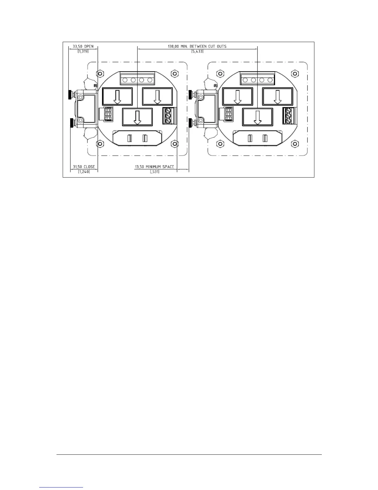
Mounting two PM135 side by side
Connecting the PM135 Unit
To connect the PM135:
1. Ensure that all incoming power sources are OFF.
2. Check that you have the appropriate power supply.
3. Connect to the external CT by passing the external
CT wire through the meter CT core. Observe the
arrow that indicates the current direction.
4. In case of a retrofit application where each external
CT ends with two wires:
Pass one wire through the meter CT core.
Connect the wire to one of the meter termination
screws.
Connect the second wire from the external CT to
the termination screw.
5. Connect the measured voltage inputs
6. Connect COM1 – RS-485 communication port
7. Connect the Power Supply inputs using 1.5
mm
2
/14AWG-dedicated wires.