4 MICRA SATEL
2. DESCRIPTION OF ELECTRONICS BOARD
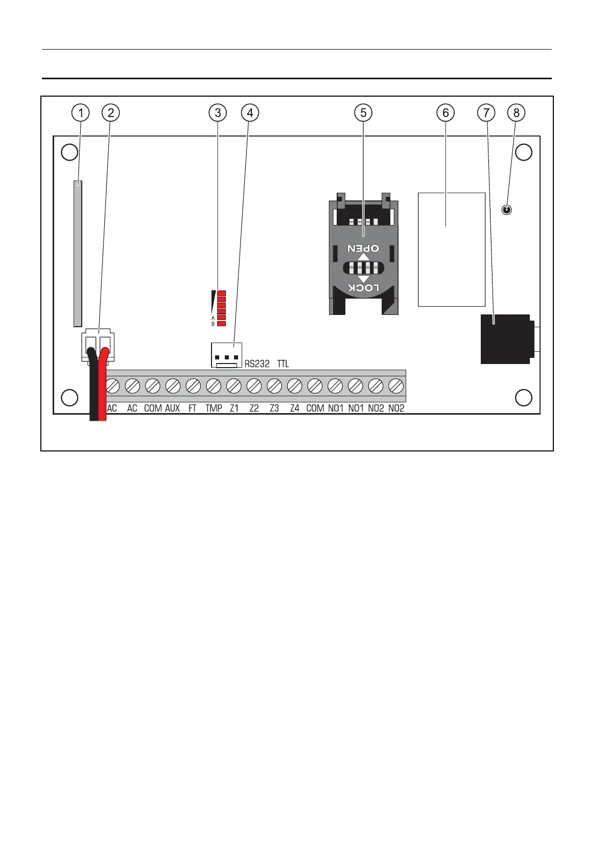
Fig. 1. View of module electronics board.
Explanations for Figure 1:
1 - superheterodyne receiver, high sensitivity, immune to spurious signals.
2 - battery connection cables
3 - LEDs indicating the module status. LED A is blinking when GPRS transmission is going
on. LED B is blinking when SMS message is being sent or the module is calling (CLIP
test transmission). The other LEDs indicate the level of signal received by the GSM
telephone. LEDs A and B blinking simultaneously indicate logging into the GSM
network. In case of an unsuccessful GSM network login, blinking of the other LEDs
provides information on the troubles (see: Fig. 2).
4 - port RS-232 (standard TTL) enables local programming by means of the GPRS-S
OFT
program (connection can be made with cables included in the set manufactured by
SATEL and designated DB9FC/RJ-KPL).
5 - SIM card socket. It is not recommended to insert the SIM card into its socket before
programming the card PIN code in the module (if the card requires entering the PIN
code). If the event codes are to be sent with the use of GPRS technology, the GPRS
service must be activated for the SIM card installed in the module.
6 - GSM industrial telephone.
7 - microphone socket. The microphone enables the listen-in feature (it is recommended
to use an electret microphone).
8 - antenna socket. Be careful when connecting the antenna so as not to damage the
socket.