SATEL MICRA 7
3.2 ESTIMATION OF CURRENT CONSUMPTION
Before proceeding to installation, sum up the currents consumed by all devices to be power
supplied by the module (the calculation should also take into account the battery charging
current.). The sum of such currents must not exceed the current output of the built-in power
supply. If the sum of currents exceeds the power supply current output, an additional power
supply unit must be used.
Note: When planning connection of devices to power output, remember that the sum of
currents consumed by these devices must not exceed the maximum current-carrying
capacity of this output.
3.3 CABLING
It is recommended that straight unscreened cable be used for making electric connections
(using the twisted pair type of cable, e.g. UTP, STP, FTP is not advisable). Select cross-
section of the power supply wires so that the supply voltage drop between the power supply
and the supplied device should not exceed 1 V as against the output voltage.
When making the cabling, remember that there must be sufficient distance between the low-
voltage wires and the 230 V AC power supply wires. Avoid running the signal cables in
parallel to the 230 V AC supply cables, in close vicinity of them.
3.4 THE MICRA MODULE INSTALLATION
The module PCB contains electronic components sensitive to electric charges.
The MICRA module should be installed indoors, in spaces with normal air humidity. The
installation place should be inaccessible to unauthorized persons. When selecting the
installation place, take into consideration that thick walls, metal partitions, etc. will reduce the
radio signal range. Installation in close vicinity of electrical systems is not recommended, as it
may adversely affect the device performance.
A permanent (non-disconnectable) 230 V AC power supply circuit with protective grounding
must be available at the module installation place.
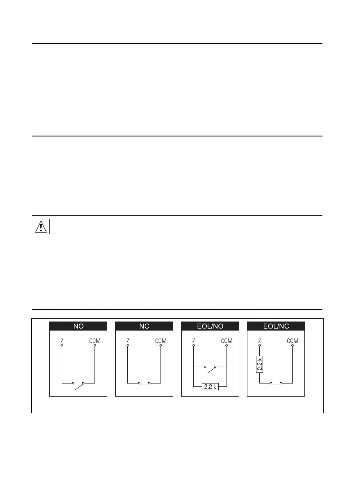
3.5 CONNECTING DETECTORS AND OTHER DEVICES TO ZONES
Fig. 4. Loop types supervised by the alarm module.
The module zones can work as:
– digital, NC type – to supervise a device with normally closed contacts,
– digital, NO type – to supervise a device with normally closed contacts,
– digital, EOL type [only in alarm device mode] – to supervise a device with normally open
or closed contacts, where an 2,2 kΩ EOL resistor is used,