24
WP33L_BA_K1_12_en_08.fm
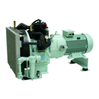
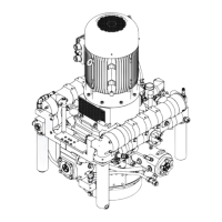
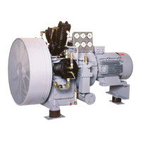
3.2 Functional description
Drive The Sauer Compressor is driven by an electric motor flange-
mounted to the crankcase bell-housing. The power is transmitted
by means of a flexible coupling. The fan on the crankshaft is part
of a fan-flywheel system.
Compressor
control
The Sauer Compressor is controlled and monitored by an electri-
cal compressor control system. This control system must comply
with the legal regulations. Optionally, J.P. SAUER & SOHN sup-
plies a suitable compressor control system.
Compression The compressor takes in ambient air through a suction filter, with
silencer, and compresses the air in two single-stage cylinders to
the final system pressure. Each cylinder is a compression stage,
followed by a cooler.
The final compression temperatures are below the flash point of
standard mineral motor oils.
The cylinders arranged in a V-configuration are equipped with la-
mellar valves, which have a long life and are easy to service.
Owing to the low compression temperatures the susceptibility of
the valves to coking or carbon build-up is extremely low.
Cooling An axial fan designed as a fan-flywheel system mounted on the
crankshaft blasts air across the cylinders, inter-coolers, valves
and oil sump. Inter-cooling takes place after each stage in zinc-
plated tube coolers.
Condensate
separation
Oil and water (condensate) accumulated during compression
and inter-cooling, is collected in the condensate separator
brehind the 2
nd
stage.