Transport and Installation
WP33L_BA_K1_12_en_08.fm
39
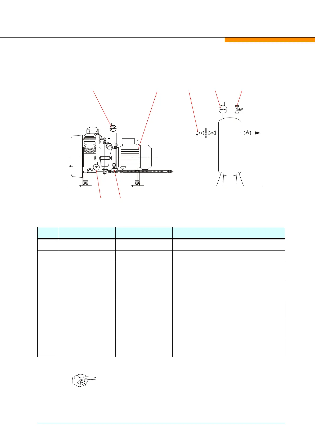
Installation The illustration below shows the connections and fittings for the
operation of a typical Sauer compressor.
Item Description Type Function
1 Drive motor AC motor Compressor drive
2 Drain valve Solenoid valve Start relief and drainage
3
Final pressure
switch
Toggle switch Stop/Start control for the compressor
4
Final non-return
valve
Valve Prevent air back-flow
5
Safety valve Spring operated
safety valve
Prevent overpressure of parts
containing pressure
6
Temperature
senso (option)
Toggle switch
Shutdown the compresor if the tem-
perature is exessive.
7
Oil level switch
(option)
Toggle switch
Shutdown the compresor if the oil
quantity is insufficient
Note!
For technical specifications of the individual items please refer to
Chapter 4.