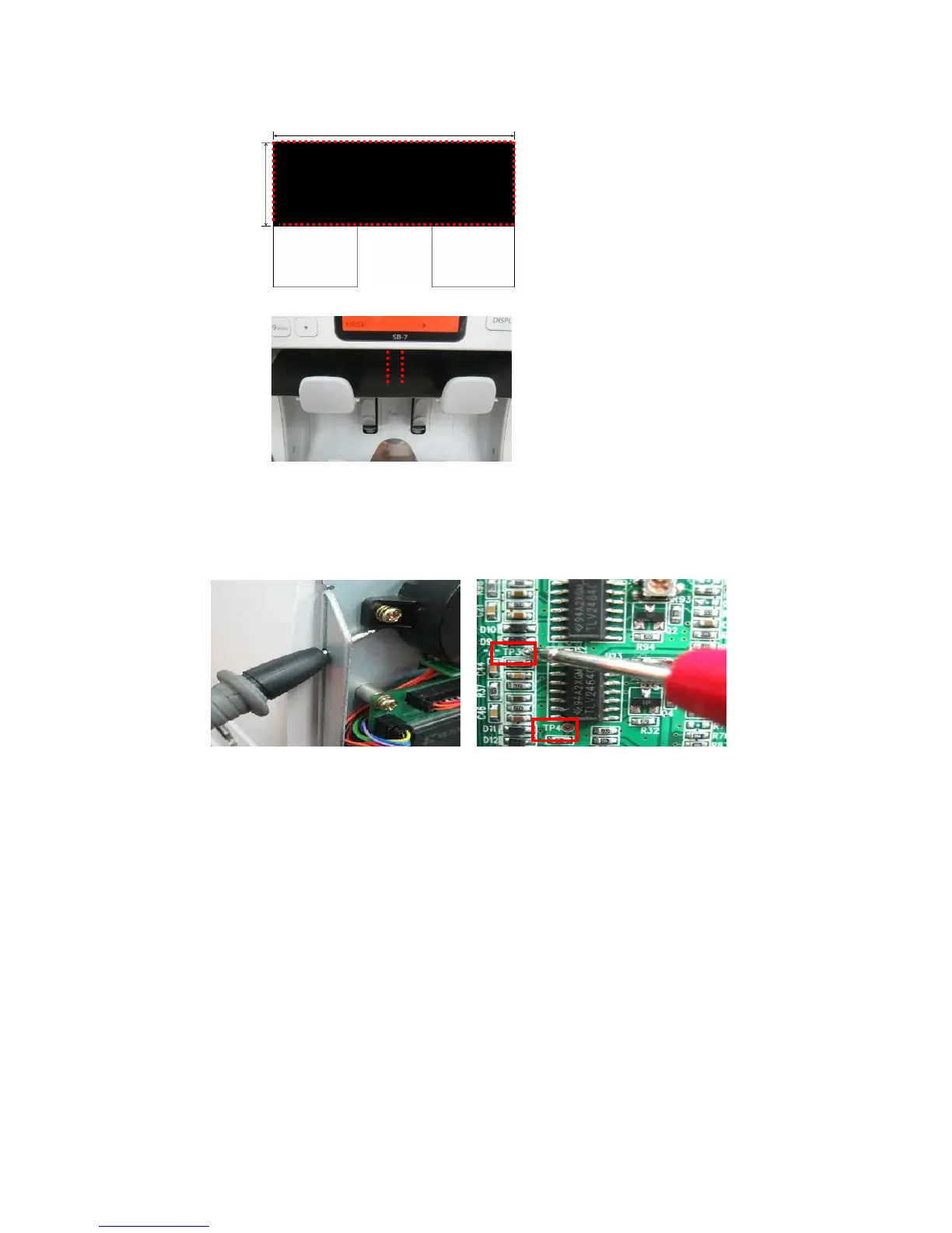
Step 3. Adjustment of ‘Reject F’
Adjust R97 (Variable Register) so that the voltage of TP3 (Test Point 3) can be 3.2V.
Step 4. Adjustment of ‘Reject R’
Adjust R35 (Variable Register) so that the voltage of TP4 (Test Point 4) can be 1.2V.
Step 1. How to make sheet for adjusting ‘Reject F’
Make sheet for adjustment with ‘IR SHADING
(DARK) Sheet’ Provided by SBM.
Cut dotted part as the image on the left side.
Step 2. Place the cut sheet on the REJECT POCKET.
At this time, black part should face upward.
80 ~ 82mm
200 mm