andthe ruler against the chock (2), as shown. Check
whetherthechockispositionedata90°totheblade.
• Ifitisnecessarytomakeadjustments,pushthechock
forwardor back untilit is perpendiculartothe blade.
Tightenthefourchocklockingscrews(1).
Caution: Ifthesawhasnotbeenusedforalongperiod
oftime,checkthatthebladepositiontothechock is
correct and adjust it if necessary.
Bevel Angle Position (fig. 14)
• Releasethebevelplatebyraisingthespringgrip(1,g.
12).
• Turnthetableleftorrighttothedesiredangle.
• Push the locking lever down and release the spring
grip.
Note: Thelevercanonlyratchetinoneofthetenpreset
positions.Thewaytolockthetableinadifferentposition
is described in the next section.
Adjusting the Bevel Table Quick Lock (fig. 14)
• Pressthelockingmechanismdownandletitratchetit.
• Turnthechocknut(5)witha13mmkeytotheleftas
shown in order to extend the closure arm against the
body of the machine.
• Check the locking mechanism to see if the plate has
been securely ratcheted in.
• Turnthesafetynut(6)totheright,asshown,tolockthe
mechanism where it is.
Note: For longer materials there are, on the right and left,
pulloutsurfaceswithhingedchocks.
Maintenance
Warning: For your own safety, switch the motor off and un-
plug the machine before your maintain or lubricate it.
General Maintenance
Wipe sawdust and dust from the machine occasionally with
a rag. Lubricate the rotating parts of the machine once a
month to extend the life of the machine.
Changing the Table Covers (fig. 7)
Warning:
• Always unplug the machine to prevent unintentional
start ups. Remove all small bits of material from the
groove in the table before beginning to saw. The table
covermayberemoved forthispurpose.It must,how-
ever,bereplacedbeforeresumptionofsawing.
• Beforebeginningtosawalwayscheckwhetherthesaw
blade can move freely and does not have contact with
the table cover. Such contact can damage the saw blade,
table cover or rotating table.
• Inordertoremovethetablecover,loosenandremove
thesixscrews(1)onthetablecover(2)withascrew-
driver.
• Toreinstallthecover,putitbackinplaceandtighten
the six screws once again.
• Checkthatthesawbladecanmovefreelybymovingthe
saw blade in the table completely through the intake
slit.
Changing the Battery (fig. 27)
Unplugthemachine. Otherwisethe machinecould start
upunintentionallyandcauseseriousinjuries.
• Removethelaserunitfromthemachine.
• Loosenandremovethetwoscrews,thenremovethela-
ser unit cover.
• Removethethreebatteries(g.27)andreplacethem
with new ones.
• Installthelaserprotectivecoveragainandtightenthe
two screws.
Note: The replacement batteries must have a voltage of 1.5
(No.LR44).
Ontheoccasionofbatteryreplacement,thelidtothebat-
tery unit must be thoroughly cleaned. Use a soft brush or
something similar to this in order to remove all sawdust
and other debris from the casing.
Changing the Belts (fig. 28, 29)
Unplug the machine.
• Loosenthescrews(1,g.28)andremovethebeltcov-
er.
• Turnthescrew(2,g.29)inananticlockwisedirection
with an Allen key in order to move the motor forwards.
• Exchangethebelts.
• Turnthescrew(2,g.29)inaclockwisedirectionwith
an Allen key in order to move the motor backwards. Do
not over tighten.
• Replacethebeltcoverandtightenthescrews.
Inspecting the Brushes
Checkthenewmotor brushesforthe rsttimeafter 50
hoursofoperation.Afterthat,checkevery10hoursofop-
eration.
Should the carbon be reduced to 6 mm in length or if the
featherorwireisburnedthroughordamaged,replaceboth
brushes. Should it be determined when the brushes have
been removed that they can still be used, then they can be
putbackintothemachine.
Conformity to European Union Standards
We, the scheppach Fabrikation von Holzbearbeitungs-
maschinenGmbH,GÜnzburgerStr.69,D89335Ichen-
hausen, hereby state that the machine described in the
following, based on its construction and manner of assem-
bly, as well as other versions we sell, are in conformity with
thepertinentregulationsoftheEuropeanUnion.
Should the machine be altered in any way, this statement
of conformity is invalidated.
Descriptionofthemachine:
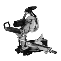
Crown and Mitre Box Saw
Machinetype:
Capas 5, Art.-Nr. 88001945
RelevantECdirectives:
EC machine directive 98/37/EG (< 28.12.2009),
EC machine directive 2006/42/EG (> 29.12.2009),
EC Low voltage directive 2006/95/EWG,
EC-EMV directive 2004/108/EWG.
Place and Date:
Ichenhausen, 14.07.2009
Signature:
In the name of, Wolfgang Windrich (technical director)
 Loading...
