Assembly
10.00 | SRU | Assembly and Operating Manual | en | 389439
31
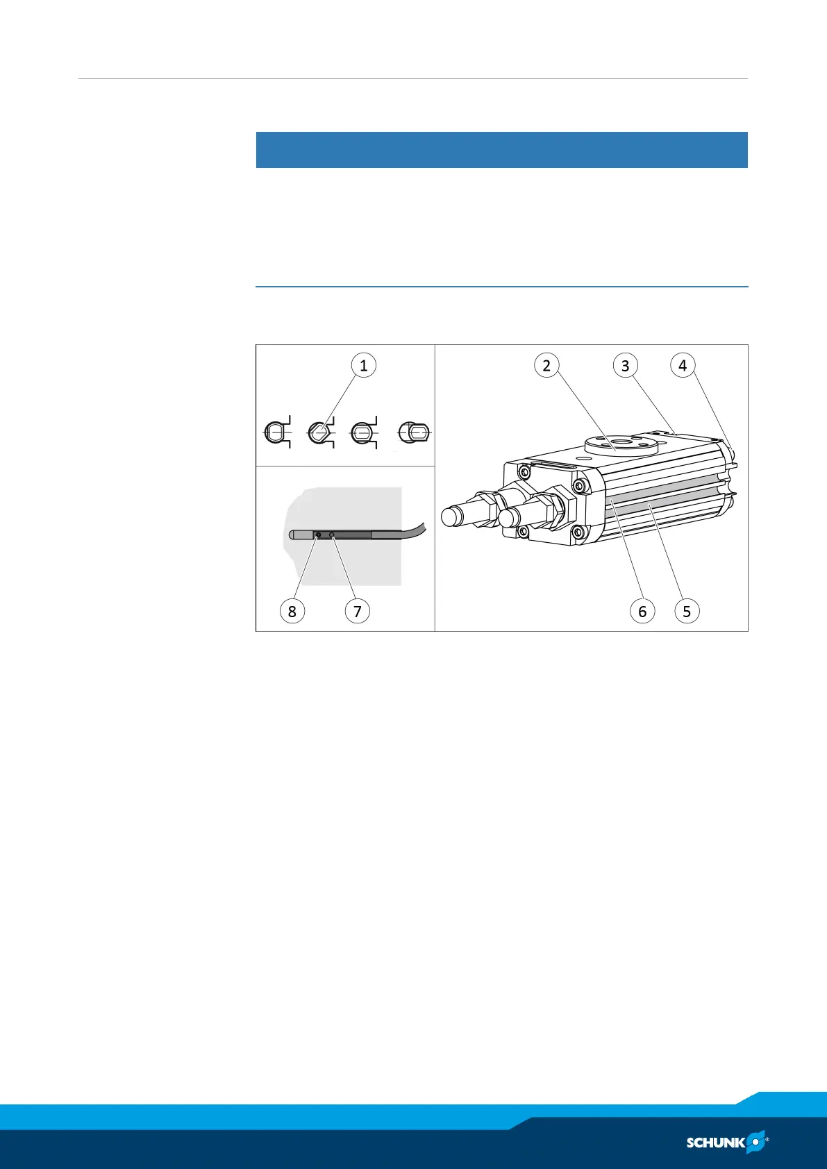
5.4.3 Mounting MMS 22-PI1 programmable magnetic switch
NOTICE
Material damage due to an incorrect tightening torque!
If the threaded pin is tightened with an incorrect tightening
torque, the product may be damaged.
• Observe a maximum tightening torque of 10 Ncm for the set-
screws.
Two groves have been worked into the housing to mount the
sensors.
Ø Connect sensor and secure cable, see sensor assembly and
operating manual.
Ø Apply air pressure to connection "A" (4).
✓ Pinion (2) swivels towards the end position.
Ø Hold teaching tool to the sensor (1) until the sensor flashes.
Ø Insert or screw the sensor (1) into the groove (5), until the
sensor flashes rapidly.
Ø Tighten set screw (8).
✓ Tightening torque: 10 Ncm
Ø Bleed connection "A" (4).
Ø Actuate connection "B" (3).
✓ Pinion (2) swivels into the other end position.
Ø Repeat steps for the second sensor.
Ø Check the switching position and test its function.
Center position
variant
Rotate unit in the center position and mount sensor analogously.
 Loading...