Accessories
05/STM-48V/en/2011-04-01/CW 41
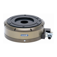
Figure 11 Connector assignment for CAN connection to MCS-12
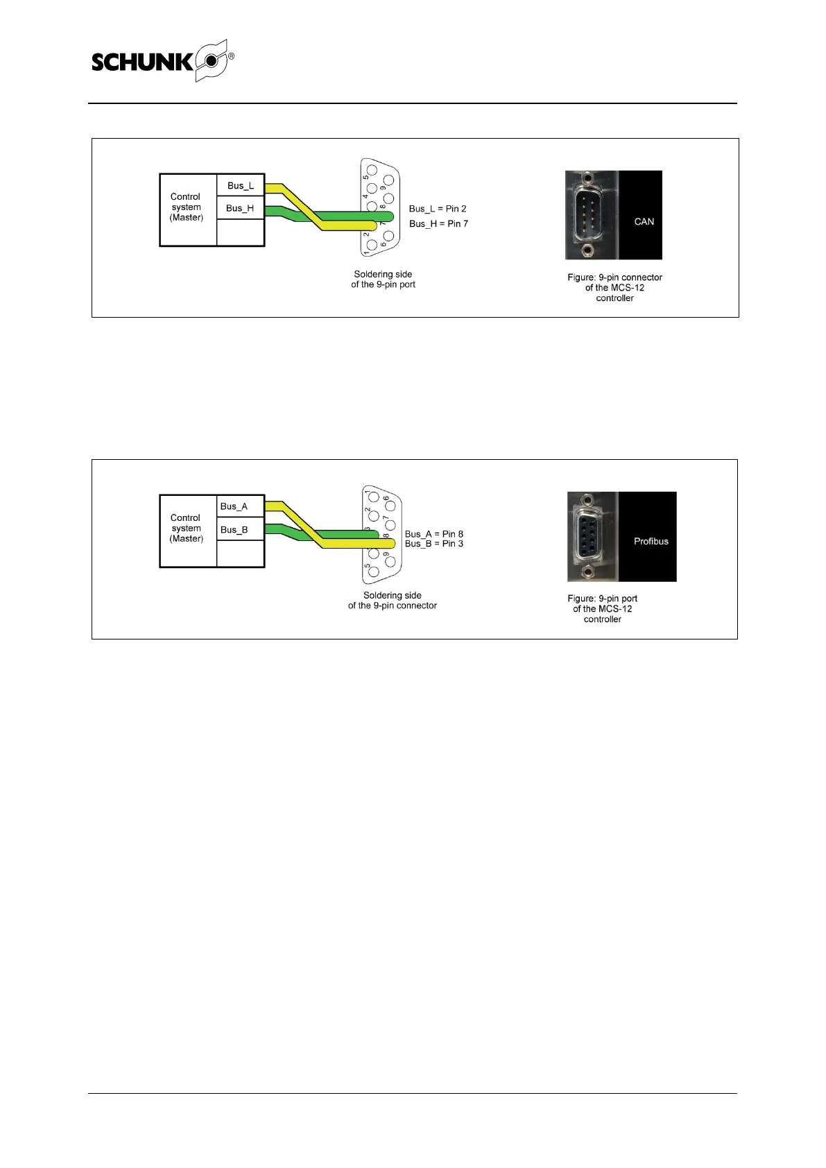
The connection is established via a 9-pin Profibus connector from
the control system (master) to the controller (MCS-12) (for the
position of the connector, see Figure 7 page 35).
Figure 12 Connector assignment for Profibus DP connection to MCS-12
Note
Depending on the field bus system, up to 255 modules can be
connected to each other.
It is recommended to use T connectors that correspond to the
field bus type. A termination resistor must be set on the last bus
node.
As an alternative to the field bus, the MCS-12 controller can be
controlled via the digital inputs and outputs.
digital inputs and
outputs