Accessories
40 05/STM-48V/en/2011-04-01/CW
Reference potential for encoder power
supply
(*)Wire color of the supplied SCHUNK cable, otherwise according to customer specifications
Table 22: Pin assignment of terminal strip X3 – pins required to connect the encoder
9.2.4 Communication interfaces
The MCS-12 currently has three communication interfaces
(RS232, CAN, Profibus DP). The controller can be controlled via
these interfaces using the SCHUNK Motion Protocol (SMP).
All communication interfaces may be connected simultaneously.
However, only one communication interface may be active.
Note
The RS232 interface should be only used as
a parameterization interface.
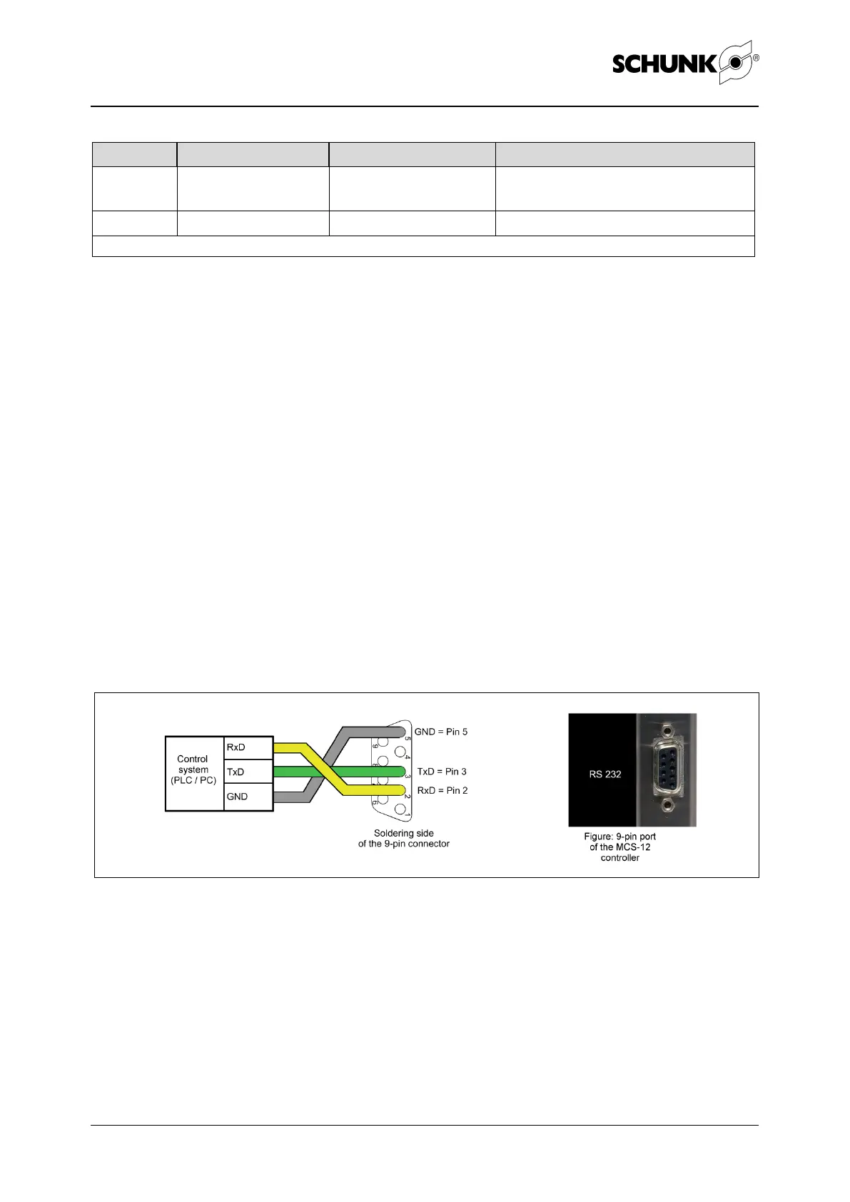
The connection is established via a 9-pin SUB-D connector from
the control system (PC / SPC) to the controller (MCS-12) (for the
position of the connector, see Figure 7 page 35)
Figure 10 Connector assignment for RS232 connection to MCS-12
The connection is established via a 9-pin SUB-D socket from the
control system (master) to the controller (MCS-12) (for the posi-
tion of the connector, see Figure 7 page 35)