10/01
3
__________________________________________________________________________________________________________________Technicals characteristics
11 - FFeeaattuurreess
Display module (
DM
)
Interface board available in 2 versions (
CB
,
CB12
) depending on customer optional equipment.
Option 3 module, option 4 module and option 5 module
(OPT 334)
Block building system enabling multiple combinations.
Note:
DM
required in all combinations
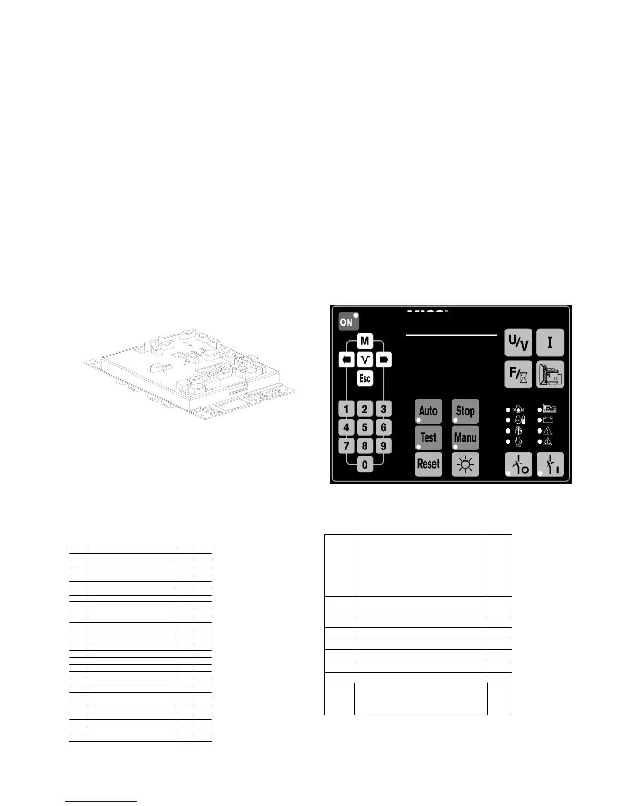
22 - DDiissppllaayy mmoodduullee
(Fig. 2)
LCD screen, 8 lines 21 characters, built-in back-light and keyboard adjustable contrast
28 momentary push buttons (two types; 10 and 13 dia.)
15 display LEDs (alarms/warnings, faults/shutdowns, status, operating modes)
UL approved polycarbonate case supplied with cable and connector for connection to the interface board
Dimensions 192x144x70
Quick installation using brackets and nuts screws
IP65 on panel face with seal (not supplied), IP20 inside
Extremely user friendly man-machine interface: multiple-message screens, diagnostic, genset status, ...
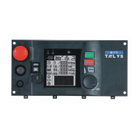
33 - IInntteerrffaaccee bbooaarrdd ((FFiigg.. 11))
CB = Main board
CB12 = Main board with option 1 and option 2 built in
Electronics in a sheet steel case (base + lid)
Dimensions : 435x263x31
Voltage bus; alternator, mains and DC built into the printed circuit board (see paragraphs 7, 8, 9 and 13)
16 bit microcontroller, (Flash, RAM and EEPROM) memories, real-time clock, battery backup for time and date
Supply from 9 to 33Volts DC and from 6Volts DC, for voltage drop at start-up
All connections are built into the printed circuit board on both sides with full screen printing
44 - LLooggiiccaall//aannaalloogg II//OO
All inputs and outputs are allocated to a specific use
(see tables below).
Note: Alarm or Fault selection via programming
Key:
A=Alarm, F=Fault, ana.=analog, C=Control
T=Transistor, R=Relay, Ω=resistive
Fig. 11 - CCB12 bboard
Fig. 22 - DDisplay mmodule
* : France only