10/01
23
This screen is used to adjust the contrast of the characters displayed. Also, when the contrast value has been
changed, only through this screen can the new value be saved in case is powered down.
Press to increase the contrast
Press to reduce the contrast
The contrast is increased or decreased in steps of 1 (..., 140, 141, 142, ...).
The contrast value which is modified by the and buttons changes on screen, thus enabling you to effi-
ciently locate the contrast area. This area varies according to ambient temperature.
Press
Esc
to exit this screen, the contrast is then saved into memory, the
GENERAL
screen appears and the
cursor flashes over the
o
sign next to
Contrast
.
________________________________________________________________________________________________________________________________________" Outputs " Menu
Viewing the outputs on an option not available (see note) or on an option module not available (factory configuration) on the cabled sys-
tem will result in the following superimposed message to be displayed.
Example: a system is configured with interface board CB12 and Option 3 module. Press
V
, when the
cursor is next to
Option 44 MModule
, to display the superimposed message opposite.
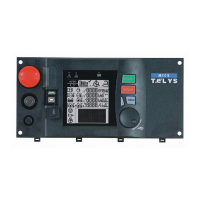
15. "" CCONTRAST "" MMENU
After validation using the
V
button, when the cursor flashes over the o sign next to
Contrast
, the
CONTRAST
screen appears as follows.
CONTRAST
Esc: Exit
<- down up ->
Current Value: 148
Adjust contrast
Min Value : 1
Max Value : 250
16. "" PPROTECT "" MMENU
If a protection of differential type (differential relay) or via constant insulation check (C.I.C.) is cabled to interface board CB12, this menu is
used to view the parameters inherent in each protection. These parameters can only be viewed if the relays (differential or insulation check)
are equipped with a specific communication.
After validation using the
V
button, when the cursor flashes over the
o
sign next to
Protect
, one of the two screens below appears, depen-
ding on the protection selected (factory configuration).
1166..11.. DDiiffffeerreennttiiaall pprrootteeccttiioonn
The " Resys M " type relay will do this function. Differential protection is used in TT neutral systems (neutral linked to earth). When the cursor
flashes over the
o
sign next to
Protect
, the
DIFF. PPROTECTION
screen below then appears.
Delay SSetting
indicates the trip time on a differential fault.
Alarm RRelay SStatus
takes two values 0 or 1 and indicates the alarm relay physical status.
Toroid CConnection
takes two values 0 or 1 and indicates the connection status of the core balance
transformer.
Fault CCurrent
indicates the % value of the fault current.
Note: The availability of option 1 and option 2 (interface board CB12) parts is detected automatically as soon as is powered up.
Example : a system comprises of interface board CB. Press
V
, when the cursor is in front of
Option 22 ((CB12)
, to make the previous screen
appear.