6
10/01
Foreword _______________________________________________________________________________________________________________________________
1. FFOREWORD
11..11.. PPrreeccaauuttiioonnss
The control unit is connected to various AC voltage sources (alternator, mains, ...).
If work inside the control panel is required, it must be performed by staff authorised to work live.
These fuses must be replaced when the generating set is in complete shutdown. For any voltage measurement on these four fuses, please
use suitable equipment.
The generating set can be equipped with a remote start-up (simple contact) or with an automatic starting system [mains failure + ATS
(Mains/Stand-by changeover switch)] .
11..22.. PPoowweerr ccoonnnneeccttiioonn
For power connection, make sure that flexible cables of suitable cross section are used to avoid overheating and a major in-line voltage drop.
Depending on laying method, ambient temperature and proximity of other cables, the conductor's cross section may vary.
11..33.. EElleeccttrriicc ccoonnnneeccttiioonnss ((ccoonnttrrooll))
Generating sset wwith mmanual sstart oonly
(from the control unit keyboard)
No external connection to make.
Generating sset wwith rremote ((without mmains) oor aautomatic ((with mmains) sstart-uup
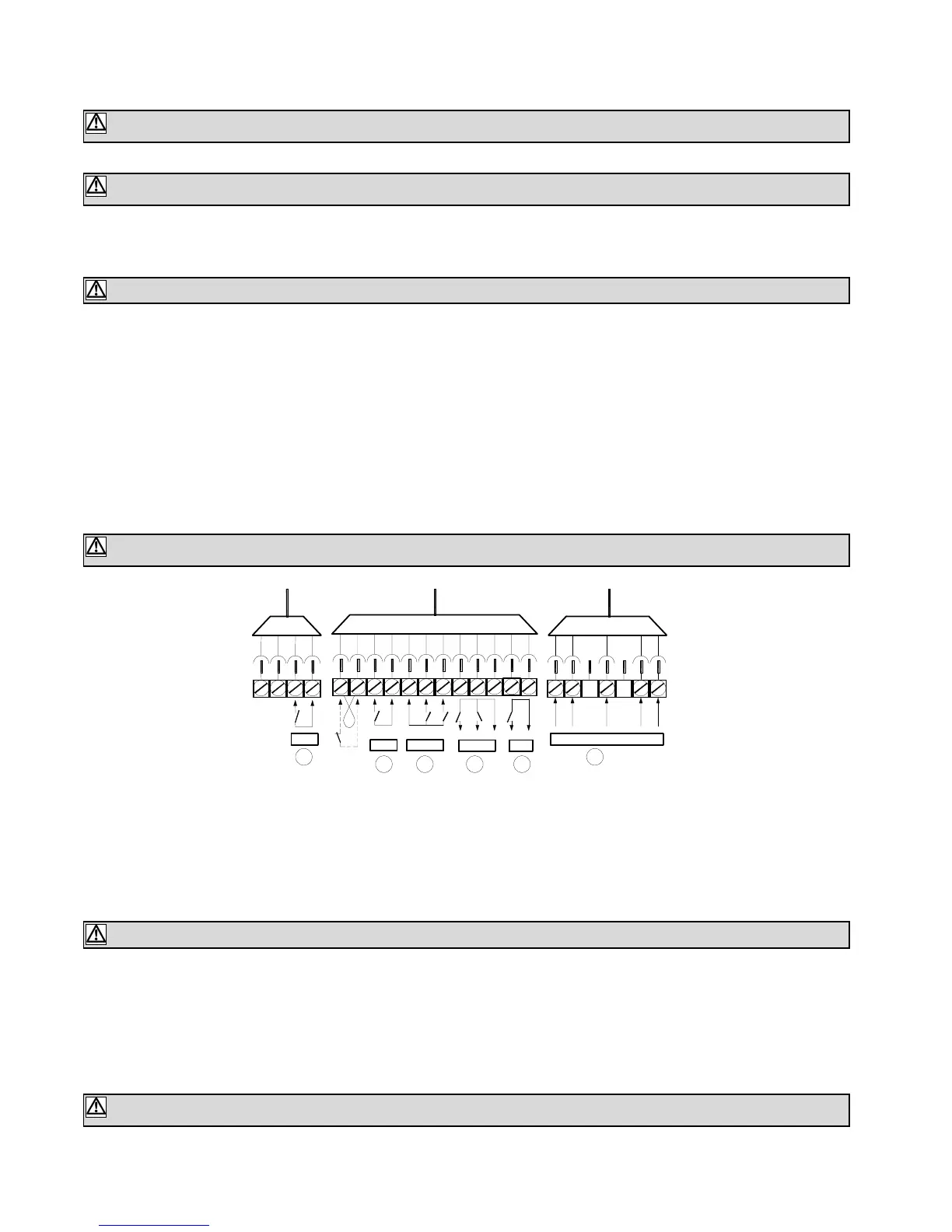
For proper operation, make the connections on the user terminal block as per the diagram below.
For DC signals, we recommend the use of a 5-core (5x1.5mm²) flexible cable between the ATS and the user terminal block.
For AC signals, we recommend the use of a 12-core (12G1.5mm²) flexible cable between the ATS and the user terminal block.
(G means cable with a Green/Yellow conductor)
Note: for a remote start only, a 2x1.5mm² flexible cable is sufficient (see overleaf)
External command (mains sensing or client contact) Output C/B fault auxiliary signal contact
Mains and Stand-by contactors home position Stand-by contactor control
Mains contactor control 1 or 3 phase water heater
If the user does not connect an ATS from our range, it is imperative to observe the board relay characteristics given below and to check
that the coils power requirements are within these parameters.
Rated ccurrent=5A Rated vvoltage=250Vac
Maximum bbreaking ccapacity uunder aa 00.7 ccos ϕϕ: 11500VA
11..44.. BBaatttteerryy pprreelliimmiinnaarryy iinnssppeeccttiioonn aanndd ccoommmmiissssiioonniinngg
The battery must be connected for the control unit to operate and the generating set to start, hence the need to check its connection:
Red wire, positive polarity (
+
),
Black wire, negative polarity (
-
).
Some generating sets are equipped with a battery isolator enabling the electric circuit to be isolated. Check that it is in the position enabling
the operation.
Beware of possible electric shock by contact with any live part, during the generating set start up.
While the generating set is idle, any work inside the control equipment is strictly forbidden as some parts of the electric and elec-
tronic equipment stay live (mains voltage available).
When the generating set is running, the fuses marked
Fn
,
F1
,
F2
,
F3
are at a dangerous potential which can lead to electric shock
when touched.
The cross sections above are given as a guide as they can vary depending on the current to be drawn, length, temperature and
control cable laying method.
Not observing the above characteristics will damage or even destroy the board control relays.
The battery is supplied without electrolyte. Fill the battery with electrolyte at least 20 minutes before any start-up attempt (see main-
tenance manual).