10/01
21
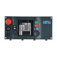
14. "" OOUTPUTS "" MMENU
After validation using the
V
button, when the cursor flashes over the
o
sign next to Outputs, the OUTPUTS screen appears as follows.
5 lines can be displayed at the same time on the screen.
The cursor flashes on the
o
sign of the first line.
Press to move the cursor to the next line, unless the cursor is on the
Option 55 mmodule
.
Press to move the cursor to the previous line, unless the cursor is on the
Main bboard ((CB)
.
Press or to place the cursor on the desired display.
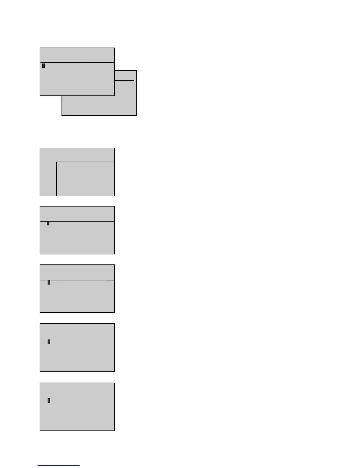
Press
V
when the cursor flashes on the
o
sign of one of the 6 lines to display the logical status
of the outputs on interface board CB or CB12, and the outputs on both option 3, 4 and 5 modules,
as described below:
- The outputs are numbered on the first line and the flashes on output 1.
- The next two lines indicate the logical status (0 or 1), symbolized by an asterisk (*).
- The last two lines indicate the cursor position and output wording.
This simple principle is used to display, in real time, how the system inputs change.
The option 5 module is simply module OPT34 configured as module 5. This module is program-
med specifically for applications with engines using integrated control electronics (MTU and Cummins engines).
The selection parameter for this module already exists in software version 1.01B. However, a line has been added in the INPUTS and OUTPUTS screens
to display the logical status of the inputs and outputs of the module in accordance with its programming.
Composition oof tthe iinterface bboards ((logical ooutputs)
CB board
(7 outputs)
CB12 board = CB board + option 1 + option 2
(7 outputs + 3 outputs + 2 outputs)
Option 33 MModule
Logical status display of the ten outputs on option 3 module.
As these outputs can be programmed, the wording on each line varies according to the programming
performed. For that reason, the wording does not appear on the screen opposite.