14
10/01
Viewing the engine parameters____________________________________________________________________________________________________________________________
All these LEDs are identified by an ISO symbol. The last two LEDs are flashing lights. The " general fault " LED flashes on appearance of any
fault and the " general alarm " LED flashes on appearance of any alarm.
Each blue coloured function button (
Stop, MManu, AAuto, TTest
) is associated with a LED. The operation of these four LEDs is described in
paragraph 2.
The
0
and
1
buttons are each associated with a LED. The operation of these two LEDs is described in paragraph 18.
The
ON
button is associated with a LED. This LED is used to display the powering up (see paragraphs 1.5 and 3.2).
Press the button to light all the LEDs for six seconds. This is only possible on the " overview " type screens.
7. SSCREEN CCONTRAST
On the various " overview " type screens, the contrast of the characters displayed on screen can be adjusted via the and buttons:
- Press to increase the contrast on screen
- Press to reduce the contrast on screen.
Note: le The contrast obtained after using the and button is not saved when if powered down. The only way the contrast value, modi-
fied by the and buttons, can be saved is via the
Contrast
menu (see paragraph 15).
Contrast adjustment is especially useful when is used in severe conditions (-15°C or +60°C).
When temperature is above +60°C, the screen is very dark. It is therefore necessary to reduce the contrast by pressing .
When temperature is below -15°C, the screen is very light. It is therefore necessary to increase the contrast by pressing .
8. DDISPLAYING TTHE AALARM AAND FFAULT MMESSAGES
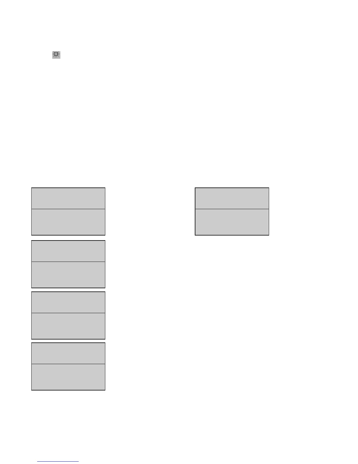
All alarms and faults are clearly viewed on screen. Two lines are dedicated for their display (see screens below).
88..11.. AAppppeeaarraannccee ooff mmeessssaaggeess oonn ssccrreeeenn
As soon as an alarm or fault appears, the electrical values and engine parameters are displayed on screen in a shortened form.
The first alarm is displayed on screen over the first of the two lines (screen 1).
The first fault is displayed on screen over the first of the two lines (screen 2).