18
10/01
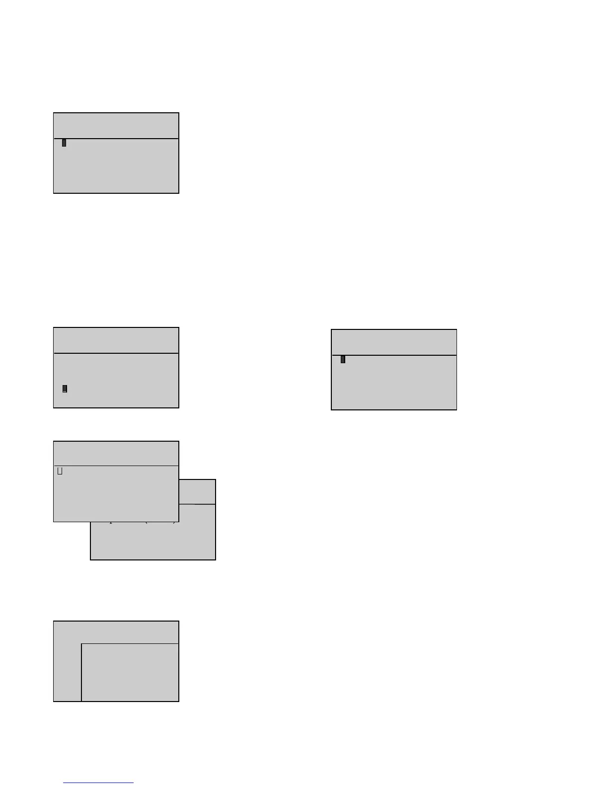
5 lines can be displayed at the same time on the screen.
The cursor flashes on the
o
sign of the first line.
Press to move the cursor to the next line, unless the cursor is on the
Option 55 mmodule
.
Press to move the cursor to the previous line, unless the cursor is on the
Main bboard ((CB)
.
Press or to place the cursor on the desired display.
Press
V
when the cursor flashes on the
o
sign of one of the 6 lines to display the logical status of
the inputs on interface board CB or CB12, and the inputs on both option 3, 4 and 5 modules, as
described below:
The inputs are numbered on the first line and the flashes on input 1.
- The next two lines indicate the logical status (0 or 1), symbolized by an asterisk (*).
- The last two lines indicate the cursor position and input wording.
- This simple principle is used to display, in real time, how the system inputs change.
The option 5 module is simply module OPT34 configured as module 5. This module is programmed specifically for applications with engines using
integrated control electronics (MTU and Cummins engines).
The selection parameter for this module already exists in software version 1.01B. However, a line has been added in the INPUTS and OUTPUTS screens
to display the logical status of the inputs and outputs of the module in accordance with its programming.
" Alarm/Flt " menu_______________________________________________________________________________________________________________________________________
- High battery voltage
- Overcranking (fail to start)
- Overspeed
- Charge alternator
12. "" SSTATUS "" MMENU
After validation using the
V
button, when the cursor flashes over the
o
sign next to
Status
, the
STATUS
screen appears as follows.
This screen is used to view the list of the date and time stamped generating set status.
Any one screen can have up to two generating set status messages.
Any stroke on the following buttons is considered as a status:
- Mode selection (
Stop
,
Manu
,
Auto
,
Test
)
- ATS (Mains/Stand-by changeover) control (
0
and
1
) in
Manu
mode only
-
ON
button.
Also, the automatic power-up, automatic shutdown and logical status of option No 20 input on option
4 module (shutdown bypass, French standard NFC 61940) are considered as statuses.
Note: For the Test and Manu buttons, only the second stroke is taken into account (i.e. confirmation of the operating mode).
Each message comprises of:
- One chronological number (from 1 to 25)
- Time (hour/minute/second) and date (day/month/year)
- Nature of the status.
Up to twenty-five status messages can be recorded into the interface board CB or CB12 memory.
These messages cannot be erased. When the list is full (twenty-five messages), the twenty sixth message will make the first recorded message
disappear and so on.
Press to view the list in ascending order (from number
1
to number
x
,
x
being the biggest number) or in other terms from the newest to
the oldest message.
Press to view the list in descending order (from number
x
to number
1
,
x
being the biggest number) or in other terms from the oldest to
the newest message.
The messages are always displayed two at a time (see the two screens below). The left-hand side screen shows messages number
1
and
2
. The right-hand side screen shows messages number
2
and
3
, after button was pressed.