3.2.2 - Mechanical checks
Before starting the machine for the rst time, check that:
- the xing bolts on the feet are tight,
- the cooling air is drawn in freely,
- the protective grilles and housing are correctly in place,
- the standard direction of rotation is clockwise as seen from
the shaft end (phase rotation in order 1-2-3). For anti-clockwise
rotation, swap 2 and 3.
- the winding connection corresponds to the site operating
voltage (see section 3.3).
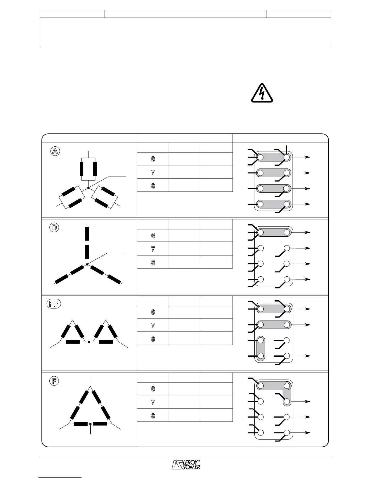
3.3 - Terminal connection diagrams
To modify the connection, change the position of the terminal
cables. The winding code is specied on the nameplate.
Any intervention on the alternator terminals during
reconnection or checks should be performed with the
machine stopped.
R 250 voltage sensing:
0 => (T8) / 110 V => (T11)
R 438 voltage sensing:
0 => (T3) / 220 V => (T2)
Connections codes
L.L voltage
Winding
Winding
Winding
Winding
3 phases
3 phases
1 phase
1 phase
or
3 phases
Factory connection
R 250 voltage sensing:
0 => (T8) / 110 V => (T11)
R 438 voltage sensing:
0 => (T3) / 380 V => (T2)
R 250 voltage sensing:
0 => (T1) / 110 V => (T4)
R 438 voltage sensing:
0 => (T10) / 220 V => (T1)
LM voltage = 1/2 LL voltage
LM voltage = 1/2 LL voltage
R 250 voltage sensing:
0 => (T8) / 110 V => (T11)
R 438 voltage sensing:
0 => (T3) / 220 V => (T2)
AR
AR
AR
AR
INSTALLATION AND MAINTENANCE
LSA 43.2 / 44.2 - 4-poLe
ALTeRNAToRS
3434 en -