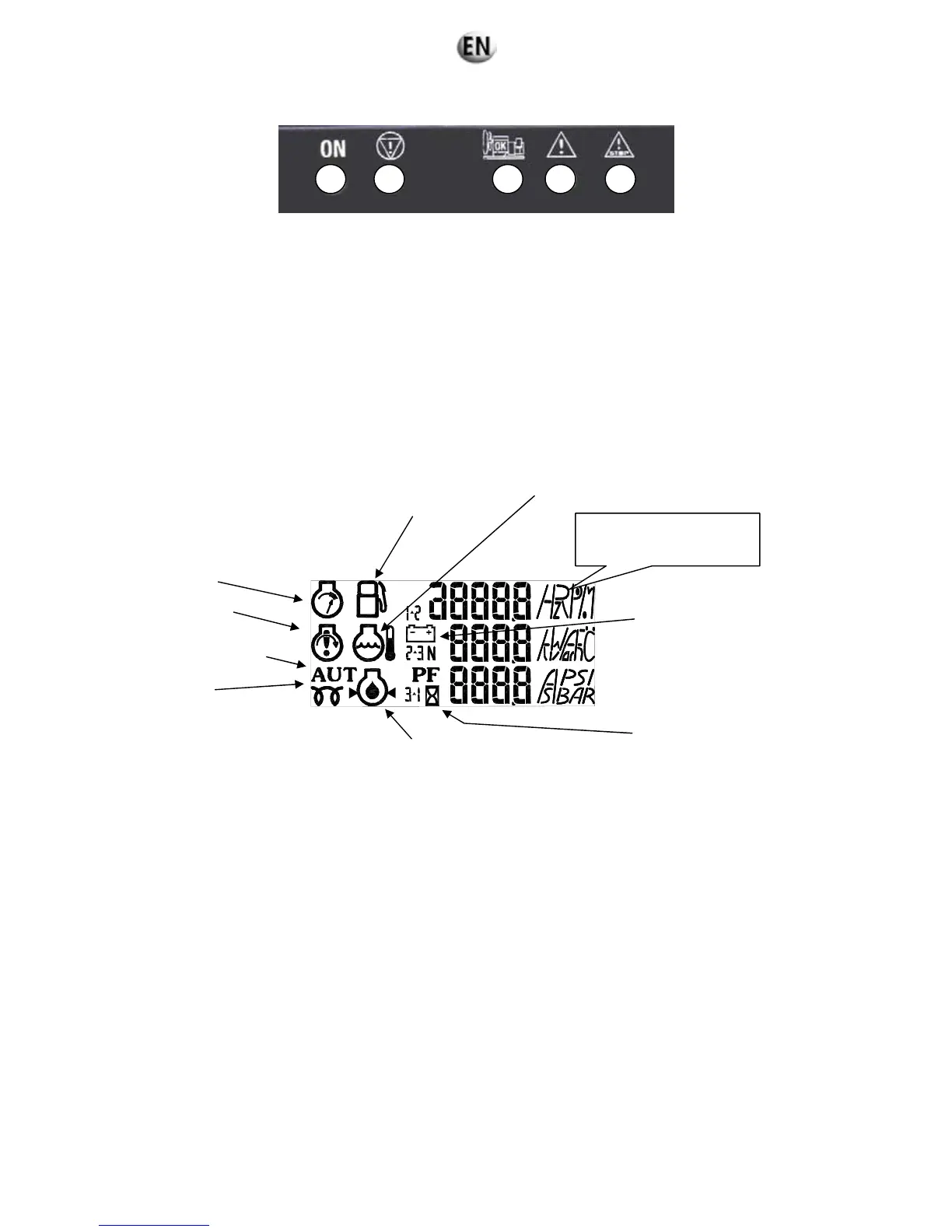
Fig. 6.2 – Description of the LEDs
A lit LED indicates:
Module being supplied (green, lights up and remains lit)
Emergency stop activated (control panel or external emergency stop) (red, lights up and remains lit)
Visualisation of starting phase and speed/voltage stabilisation (flashing) and generating set operating OK or set ready to
generate (green, lights up and remains lit)
General alarm (orange, flashing)
General fault (red, flashing).
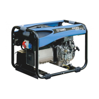
6.2.1.1. Introduction to pictograms
The pictograms are as follows:
Operating temperature
Fuel
Overspeed
Non-starting fault
Starting on external command
Preheating
Air intake
Oil pressure
Battery
Delay
Fig. 6.3 – View of pictograms
The "fuel level" pictogram is used to display the fault, the alarm and the fuel level.
The "operating temperature" and "oil pressure" pictograms are used to display the fault and analog value
The "overspeed" and "non-starting fault" pictograms are used to display the fault.
The "battery" pictogram is used to display the "alternator charge" fault and to indicate the battery voltage.
1 2 3 4 5
Symbols for electric and
mechanical sizes