Installation 14400MK2-21 C/Ku-Band TVRO
3-16
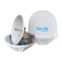
14. Loop web straps under the
Cross-Level Beam to prepare
the Pedestal for lift.
15. Hoist the Pedestal Assembly
up and into the bottom half
of the radome and install it
onto the stand using the
hardware provided. Apply
loctite to and tighten the
mount bolts.
NOTE: The circuit breaker panel
should be oriented to be facing
the radome entry hatch (AFT) so
that it is within easy reach for
powering the equipment OFF.
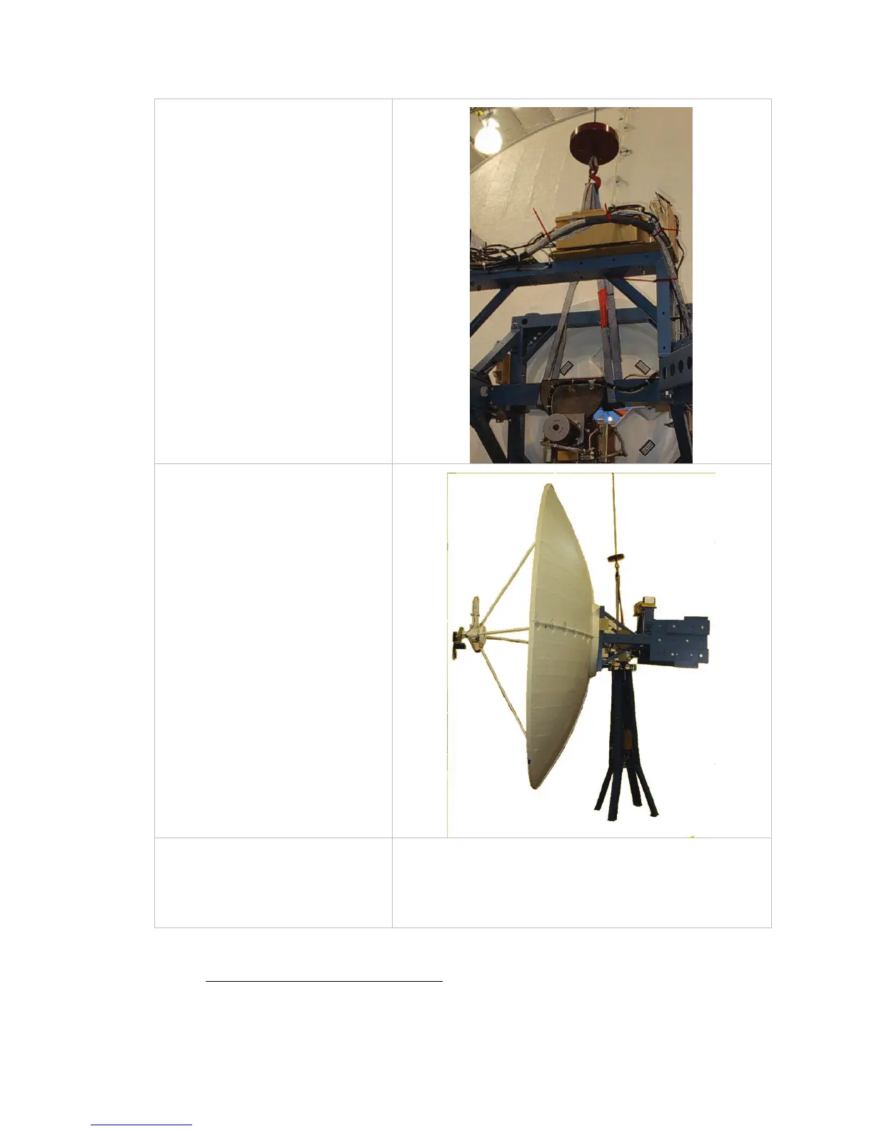
The antenna pedestal General
Assembly is now completely
assembled in the bottom half of
the radome and is ready for you to
put the top half of the radome on.
3.4.5. Close the 168” Radome Assembly
Refer to the Radome Assembly drawing for your system and the procedure below.
 Loading...