14400MK2-21 C/Ku-Band TVRO Maintenance and Troubleshooting
6-9
6.6.3. Isolating a 400 MHz Modem Fault Procedure:
1. Issue “<0000” and “>0000” queries to the ADE and BDE modems and record the responses.
ADE (>0000)______________ BDE (<0000)______________
2. Compare your recorded responses to the list below to determine what modem fault(s) (if any) is present.
3. Use the appropriate text following the failure table for a list of possible failures attributed to the failure
type established.
Tools suggested:
Laptop or PC w/ an available comport and
diagnostic software installed
ProgTerm Ver. 1.35 or Later
DacRemP Ver. 0.20 or Later
9 pin Serial cable Straight thru (1-1 Pin out) For Serial Based
Connections
CAT5 Cross-over cable Required for IP based connections (HTML, DacRemP IP)
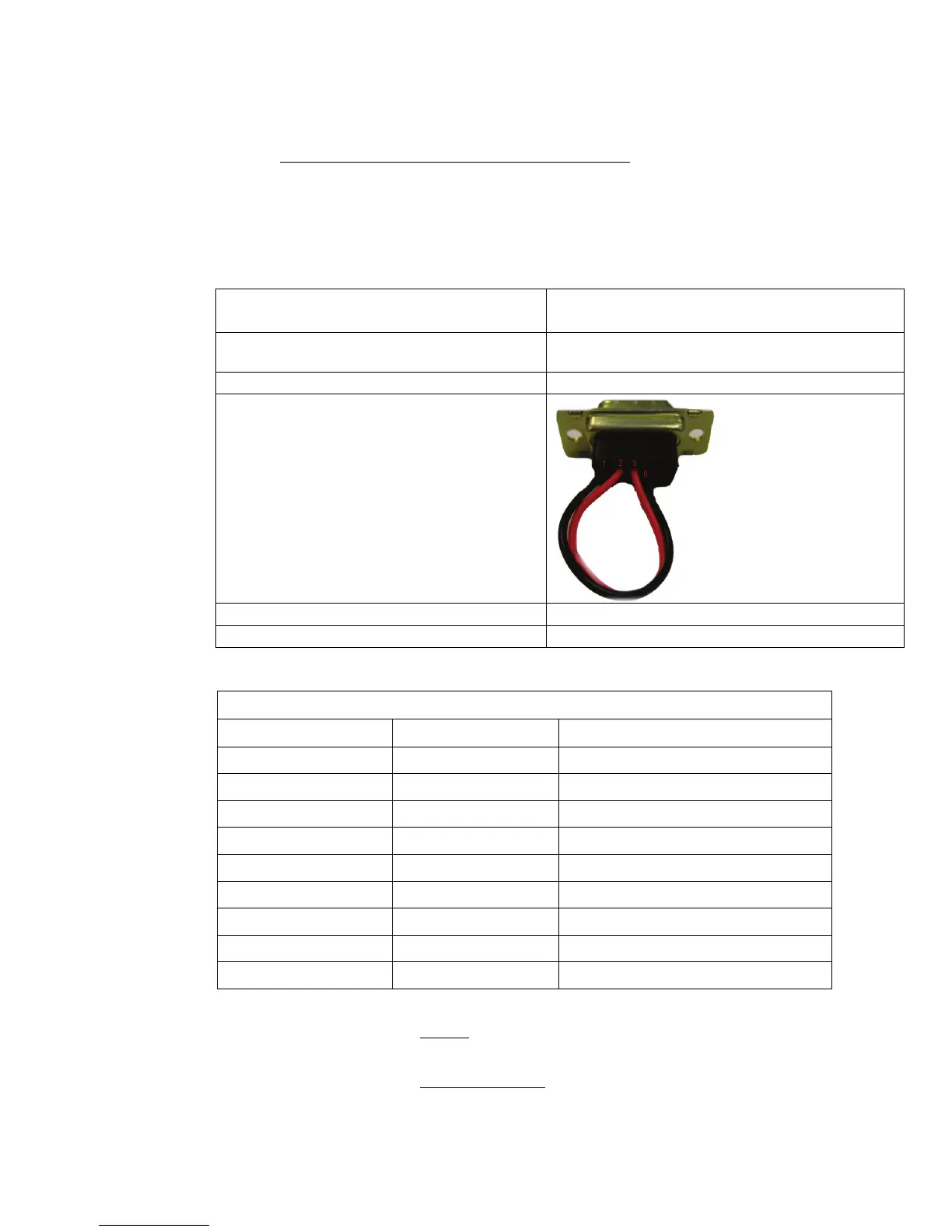
Serial Loopback Connector
Build a Loop Back Test Adapter by Shorting Pin 1
to Pin 8 and Shorting Pin 2 to Pin 3 on a female
DB9(S) connector.
Spectrum Analyzer Capable of handling 100kHz up to 3Ghz & up to 48VDC
SMA “T” splitter or N type “T” splitter Or equivalent cabling
400MHz FSK Modem Fault Reference Table
ADE Modem RSSI BDE Modem RSSI Failure
P= <65, R= <65 P= <65, R= <65 None
P= >65, R= >65 P= >65, R= >65 Receive IF Path
No Response No Response BDE/ADE No Response
No Response P= <65, R= <65 ADE No Response 1
No Response P= >65, R= >65 ADE No Response 2
P= <65, R= <65 P= >65, R= <65 BDE Receive Or ADE Transmit (PED M&C)
P= <65, R= >65 P= <65, R= <65 BDE Transmit Or ADE Receive (PED M&C)
P= <65, R= <65 P= <65, R= >65 BDE Receive Or ADE Transmit (RF M&C)
P= <65, R= >65 P= <65, R= <65 BDE Transmit Or ADE Receive (RF M&C)
6.6.3.1.1. NONE:
No failure communication failures between ADE and BDE modems.
6.6.3.1.2. Receive IF Path:
The Following possibly points of failures assumes LED illumination on both modems.
1. Modem Configuration
 Loading...