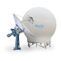
14400MK2-21 C/Ku-Band TVRO Maintenance and Troubleshooting
6-23
one location on the equipment frame to the same location on the opposite side of the equipment
frame (ie from the top left of the reflector mounting frame to the top right of the reflector
mounting frame). Do NOT add counter-weight during this step.
4. Last, balance the antenna with the elevation pointed at, or near, zenith (referred to as top to bottom
balance) by moving existing counter-weights from the top to the bottom or from the
bottom to the top. Always move weight from one location on the equipment frame to the same
location on the opposite side of the equipment frame (ie from the top left of the reflector
mounting frame to the bottom left of the reflector mounting frame). Do NOT add counter-weight
during this step.
5. When completed, the antenna will stay at any position it is pointed in for at least 5 minutes (with no
ship motion).
6. Do NOT cycle antenna power to re-Initialize the antenna. Return to the ACU, which is still in
REMOTE BALANCE mode, and press ENTER to exit Remote Balance Mode. When you exit Balance
Mode the antenna will be re-initialized, which turns DishScan®, Azimuth, Elevation and Cross-Level
drive ON.
6.8.2. To Adjust Tilt:
A REMOTE TILT calibration is required to align the level cage assembly correctly so that all sensors will be
aligned accurately to the axis they relate to. The fluid filled tilt sensor provides a two dimensional horizon
reference. The system is not able to automatically calculate the exact center value, therefore it is necessary
to perform this procedure to manually enter any offset required to make sure the PCU receives a true
reference to the horizon. The procedures below describes the process of performing this calibration from
either the ACU front panel or DacRemP diagnostic software by connecting the ACU’s RS-422 M&C Port to an
available serial port on a Laptop/Desktop computer using a standard 9 pin serial cable.
Step 1 Turn Off DishScan Drive.
Using the DAC2202 ACU Front Panel:
1. Go to Remote Command window by pressing and holding the two LEFT & RIGHT arrows
until the EL TRIM parameter is displayed.
2. Press and release both Left & Right arrow keys again. The “SAVE NEW PARAMETERS”
window should now be displayed.
3. Press either the
ENTER key or the DOWN key until the “REMOTE DishScan
TG” parameter is displayed.
4. Press the
“RIGHT arrow to activate selection, then press the Up arrow to toggle
state to OFF. Press the
ENTER key (Note: You will see that an error code 16 is
generated when DishScan movement is off.)
Using DacRemP:
1. Click on the icon in the Comm Diagnostics window. (Verify that DishScan
is turned off by clicking the Error LED on main display panel, there should be a check mark
next to Conscan/DishScan)
(Steps 2-7 will require assistance to observe and operate antenna simultaneously)
Step 2: At Antenna, If not already installed, place a circular level bubble on top lid of level cage.
Step 3: On the ACU front Panel, press either the ENTER key or the DOWN arrow key until
the REMOTE TILT window is displayed
Step 4: Push the RIGHT arrow key to activate the Remote Tilt Mode.
Step 5: Based on the feedback from the technician observing the circular bubble, the technician which
operating the ACU will need to use the arrow keys to rotate the stabilized antenna mass from front to
back and left to right. You should wait at least 10 seconds between commands to allow time for sensor
to settle.
 Loading...