Introduction ST94-21 C/Ku-Band TVRO
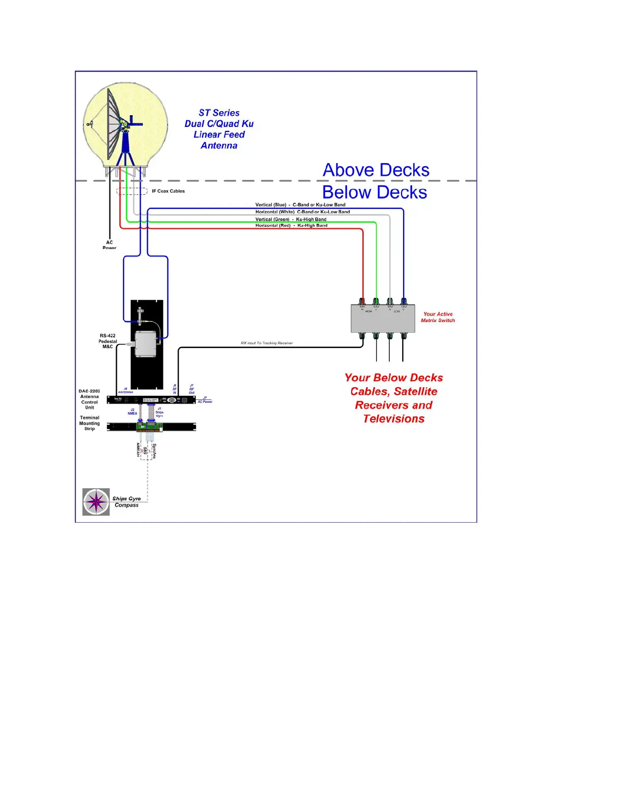
Figure 1-1 TVRO Simplified Block Diagram
1.4. Dual Antenna Configuration
Sometimes, due to very large blockage conditions, you may need to install a dual antenna configuration to provide
uninterrupted services. Two full antenna systems are installed and the ACU control outputs are connected to an
arbitrator switch panel which then is connected to the below decks equipment. NOTE: The RXIF from EACH antenna
MUST be connected to the RF IN (J6) on the rear panel of its respective ACU then RFOUT (J7) is connected to the RXIF
input of the Dual Antenna Arbitrator. This connection scheme is required for ACU “A” to be able to control Antenna
“A” (and ONLY Antenna “A”) AND ACU “B” to be able to control Antenna “B” (and ONLY Antenna “B”).
You will program the blockage zone(s) for each of the two antennas (refer to Setup – Blockage Zones). The blockage
output from the ACU is fed to the Terminal Mounting Strip so that the output of each ACU can be connected to the
arbitrator panel to control it. The blockage output is available on SW2 terminal of the Terminal Mounting Strip to
provide a transistor “short” to ground when the antenna is within a blockage zone programmed into the ACU. When
not blocked the SW2 terminal will be an “open”.
When one antenna is blocked, its blockage output will command the arbitrator panel to switch services to the Satellite
TV receivers from that antenna to the other antenna. The arbitrator panel provides a logic latch to prevent excess
switching when the ship heading is yawing, therefore, causing if the antenna to be repeatedly blocked – unblocked –
blocked.
EAR Controlled - ECCN EAR99