ST94-21 C/Ku-Band TVRO Maintenance and Troubleshooting
13.3. 400MHz Modem Configuration
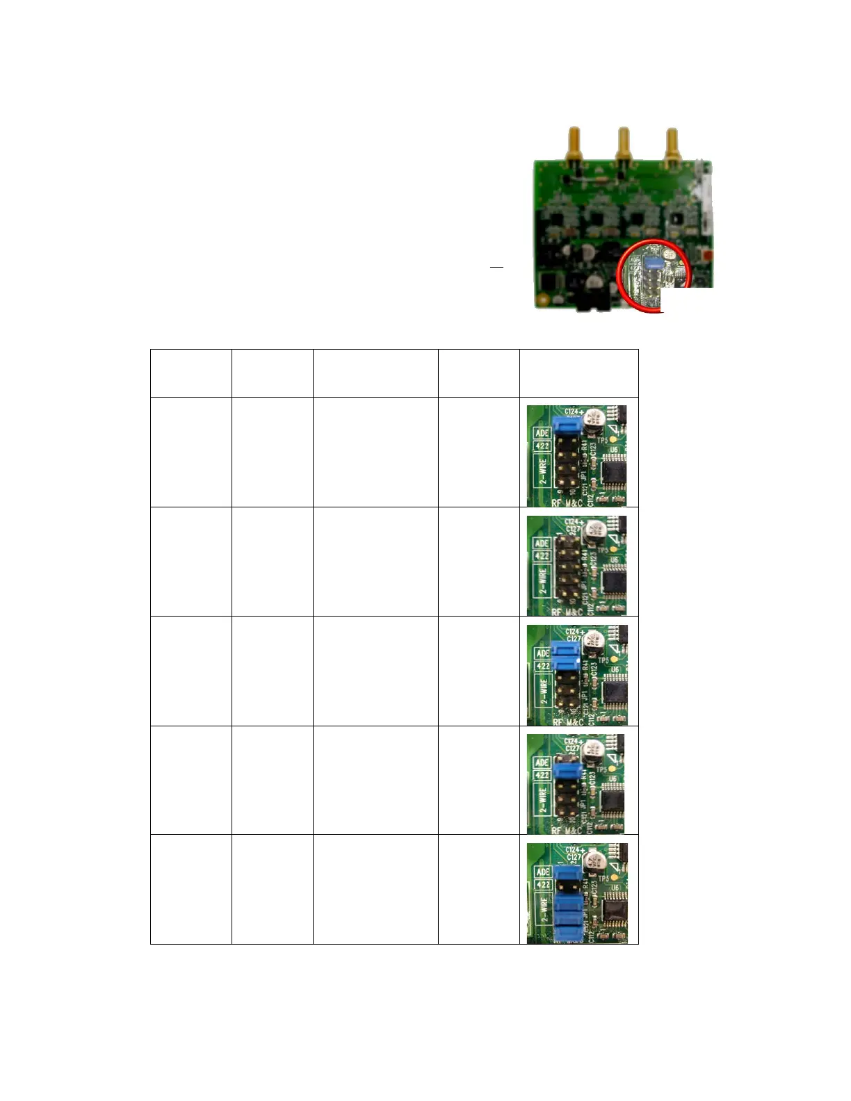
The 400MHz FSK modem PCB has a jumper block (located
component side of PCB) that is used to configure it for Above
Decks or Below Decks operation as well as to configure its’ serial
communications protocol (RS232, RS422, or RS485). Based on
the desired mode of operation, the appropriate jumper(s) will be
installed at the factory, prior to shipment of a completed system.
In general, no field modifications to these jumper settings are
required, except when it is required to re-configure a modem to
operate in a different mode of operation ( i.e. converting a spares
kit below decks modem to operate as an above decks modem or
re-configuring an ADE Modem for M&C integration with a newly
installed RF package change that requires RS485 communications
instead of RS422). Refer to the table below for the proper jumper
settings.
Dash
Mounting
Communication
Jumper
Settings
Visual Jumper
Reference
-1
Above
Decks
RS232 1-2
-2
Below
Decks
RS232 None
-3
Above
Decks
RS422
1-2
3-4
-4
Below
Decks
RS422 3-4
-5
Above
Decks
2 Wire RS485
(Half Duplex)
1-2
5-6
7-8
9-10
EAR Controlled - ECCN EAR99