ST94-21 C/Ku-Band TVRO Installation
12. Use tie-wraps to attach the reflector harness
and coax along the dish strut, around the side of
the dish, to the back side of the dish. Assure
that you leave sufficient slack in these
cables for full rotation of the feed.
13. Attach the 15 pin connector on the antenna
reflector harness to the shielded Polang Aux
Relay box.
14. Connect the IF receive coax cables from the
feed to the Receive inputs on the panel of coax
switches according to the block diagram.
The antenna pedestal General Assembly is now
completely assembled in the bottom half of the
radome and is ready for you to put the top half of
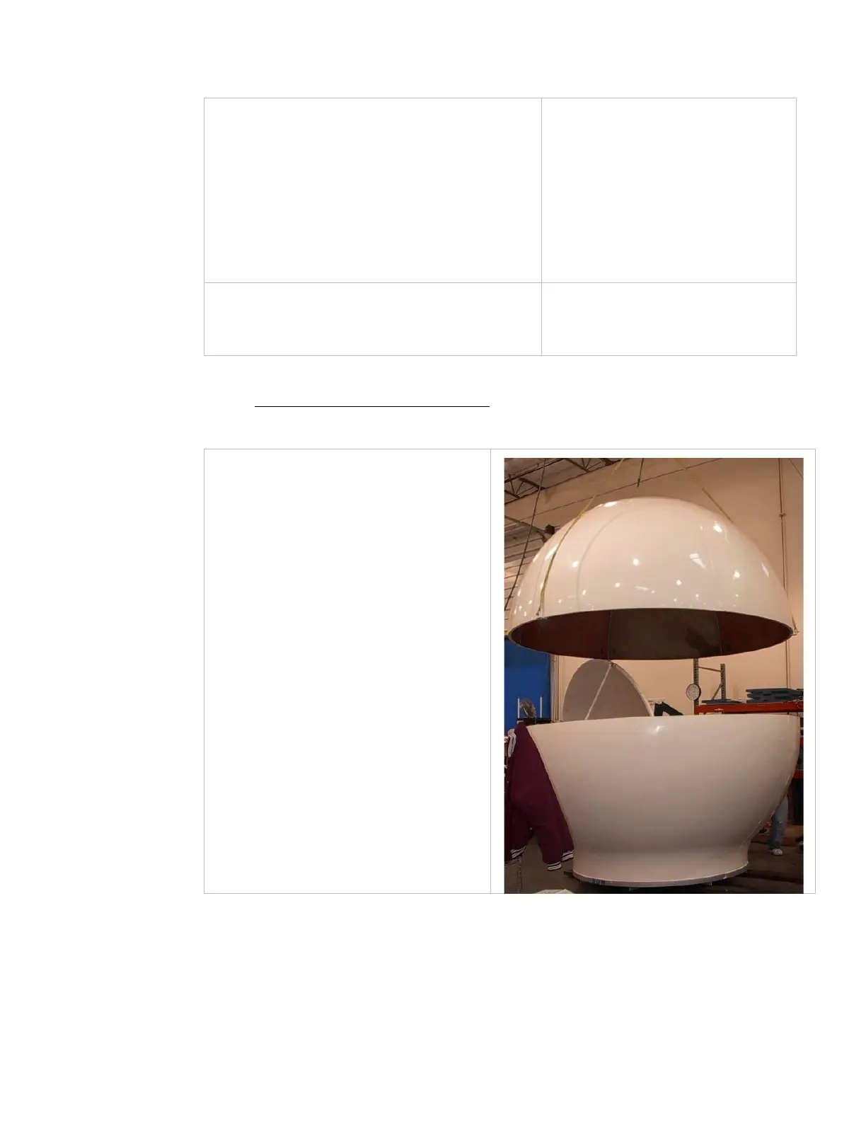
3.8.7. Close the 144” Radome Assembly
Refer to the Radome Assembly drawing for your system and the procedure below.
1. Lift Upper section up over the dish &
feed assembly and set it down onto
the lower section.
EAR Controlled - ECCN EAR99