Installation ST94-21 C/Ku-Band TVRO
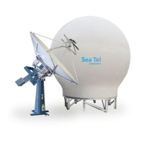
• This chart displays the Torque Command errors for each axis via three traces, CL (Cross Level), LV
(Elevation), and AZ (Azimuth), at a fixed 0.195 amps/vertical division.
• In all axes, tracing centered on the reference line means that that axis drive is neutral. Tracing
above the reference line means that that axis is being driven CCW. Tracing below the reference
line means that that axis is driving CW.
• A normal trace display will be ± 1 divisions from the red reference line while under calm sea
conditions and with DishScan® Drive turned off, as shown below.
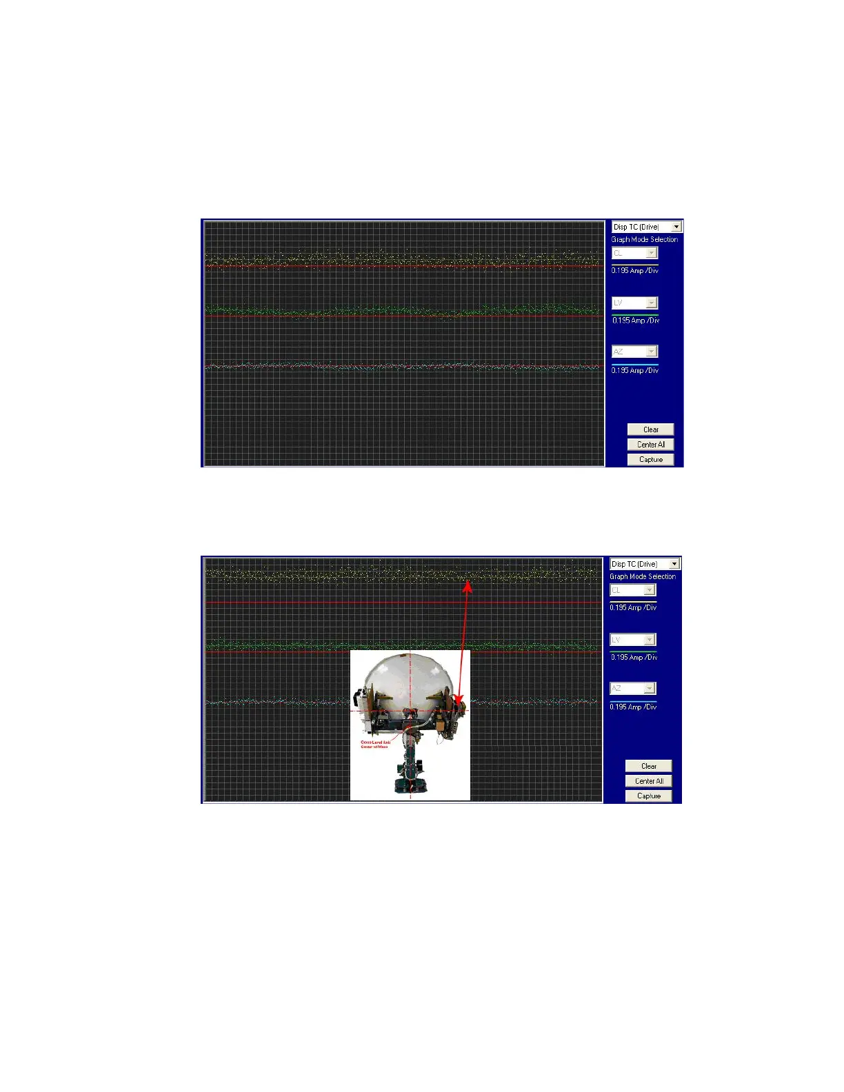
• The Cross Level displayed above the reference line indicates that the CL axis is being driven CCW
(Left in CL).
Example: The antenna pictured in the screen capture below is imbalanced so that it is “Right Heavy”.
The CL trace is plotting above the red reference line, indicating that CCW drive is required to keep
the Cross-Level beam level to the horizon.
• The Level display will plot below the reference line when the antenna requires CW drive (Up in
elevation).
Example: The antenna pictured in the screen capture below is imbalanced so that it is “Front, or
Bottom, Heavy”. The LV trace is plotting above the red line, indicating that the LV axis is being
driven CW to maintain the current elevation position.
EAR Controlled - ECCN EAR99