ST94-21 C/Ku-Band TVRO Maintenance and Troubleshooting
Tools suggested:
Laptop or PC w/ an available comport and
diagnostic software installed
ProgTerm Ver. 1.35 or Later
DacRemP Ver. 0.20 or Later
9 pin Serial cable Straight thru (1-1 Pin out) For Serial Based
Required for IP based connections (HTML, DacRemP IP)
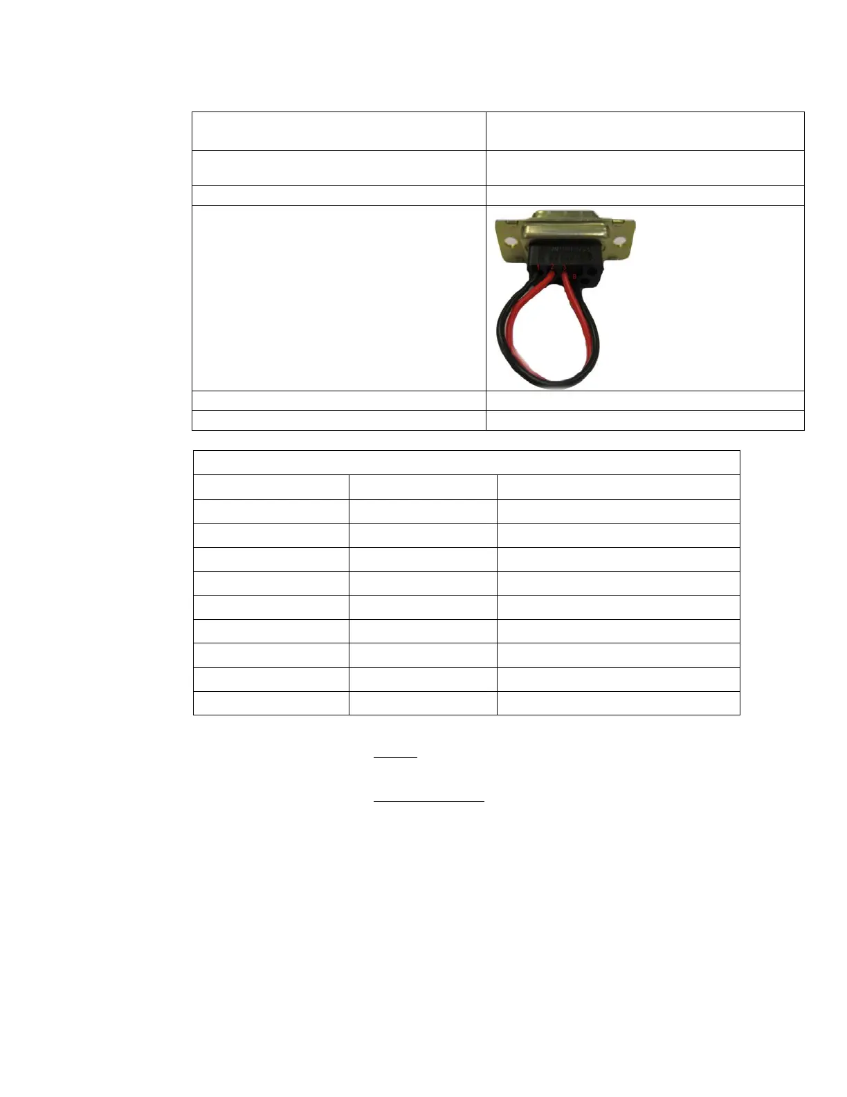
Serial Loopback Connector
Build a Loop Back Test Adapter by Shorting Pin 1
to Pin 8 and Shorting Pin 2 to Pin 3 on a female
DB9(S) connector.
Capable of handling 100kHz up to 3Ghz & up to 48VDC
SMA “T” splitter or N type “T” splitter
400MHz FSK Modem Fault Reference Table
BDE Receive Or ADE Transmit (PED M&C)
BDE Transmit Or ADE Receive (PED M&C)
BDE Receive Or ADE Transmit (RF M&C)
BDE Transmit Or ADE Receive (RF M&C)
13.6.3.1.1. NONE:
No failure communication failures between ADE and BDE modems.
13.6.3.1.2. Receive IF Path:
The Following possibly points of failures assumes LED illumination on both modems.
• Modem Configuration
Verify BDE modem and ADE modem are properly configured (jumper block settings).
• Coax Cable failure
Verify continuity on the below coaxes, repair or replace as required.
o BDE Modem to connector bracket (Base Rack Panel Assembly)
o (CFE) BDE to ADE Rx IF (Base Rack Panel to radome Connector bracket)
o Rx N to SMA Adapter (Located on connector bracket at radome base)
o SMA to SMA (From connector bracket to bottom the bottom side of the
rotary joint)
o SMA to SMA (From top side rotary joint to PCU/ADE Modem
EAR Controlled - ECCN EAR99