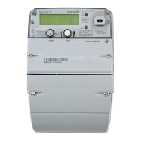
Figure 2: Sprint 211 electricity meter
Fixed Plate–Information is fixed and is common for all meters of this type.
1. LCD display - A large multi-segment LCD supporting alpha-numeric characters displays the information
and values for various electrical parameters recorded by the meter.
2. Push Buttons - Two push buttons Left and Right, allow interactions with Sprint 211. These buttons are
used for various user operations such as display navigation, boost operation etc.
3. Communication Module – To facilitate AMI communication, Sprint 211 provides a modular compartment;
into which, a communication module can be fitted as required.
4. Metrological LED (Fixed) - This LED is provided on the meter main face plate and flashes according to the
rate of energy consumption measured by the meter. It is used for testing the accuracy of the meter and as a
visual indication of the rate of energy consumption.
5. Metrological LED (Configurable) - This LED is provided on the meter main face plate and by default it is
configured for Reactive Import Energy consumption.
6. 1107 Port – The communication with the external world is supported through 1107 optical port. The port
supports a maximum data rate of up to 9600 baud.
7. Meter Base and Front Cover - The base or enclosure of the meter is made of a high-grade fire-retardant
poly-carbonate. The front cover, made of the same material, is fastened to the base with screws. A sealing
arrangement is provided to prevent tampering.
8. Sealable Screws - These screws facilitate the sealing arrangement necessary after the installation of the
meter in the field.
9. Supply LEDs: Two supply LEDs are provided on the meter main face plate for indicating main switch status
such as OFF, ON and ARM state.
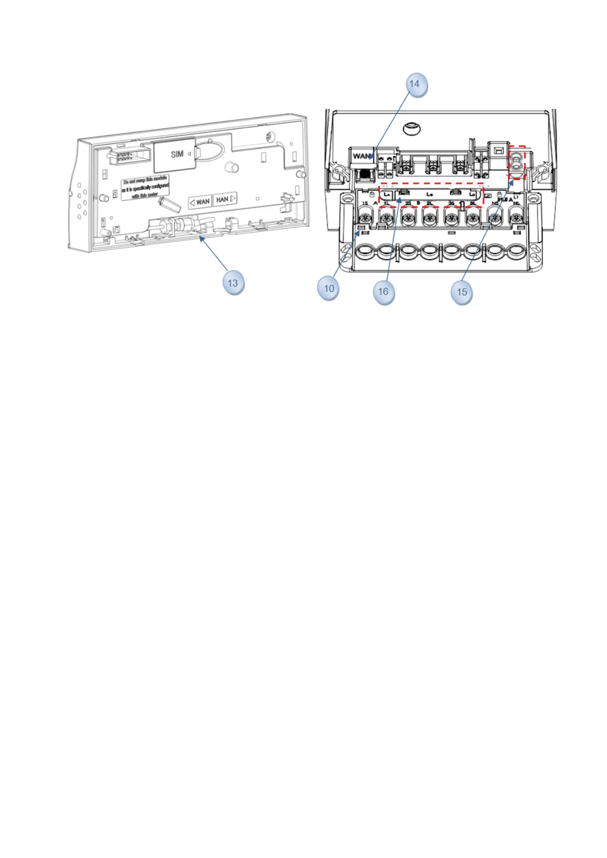
10. Terminals and Terminal Block - A terminal block, capable of sustaining high temperature, is provided in
the meter with adequate provisions for connecting wires to the meter.
11. Secondary Terminal Cover- The secondary terminal cover provides additional protection for the live
terminals of the meter and keeps them inaccessible even after removal of the main terminal cover.
12. Terminal Cover–The terminal cover protects the terminal connections from tamper or interference,
provides safety from hazards and provides security of add-on modules.
13. SMA connector for external antennas - SMA (Sub-Miniature version A) connectors are available under
the module to connect a compatible external antenna (WAN and HAN) on the Sprint 211.
14. RJ 45 Port: This port is not accessible to the user.
Page 10 of 48 Sprint 211 Installation Manual BGX701-160-R01