4.7.4 Making connections
1. Insert each conductor core into the appropriate connection cage. Insert each cable into the terminal
box shroud. Connect load side first, i.e. 1L, 2L, 3L, NL and then the supply side, 1S, 2S, 3S, NS.
Ensure that no exposed conductor is visible outside the terminal block shroud and
approximately 5.00 mm insulated length is inside the shroud.
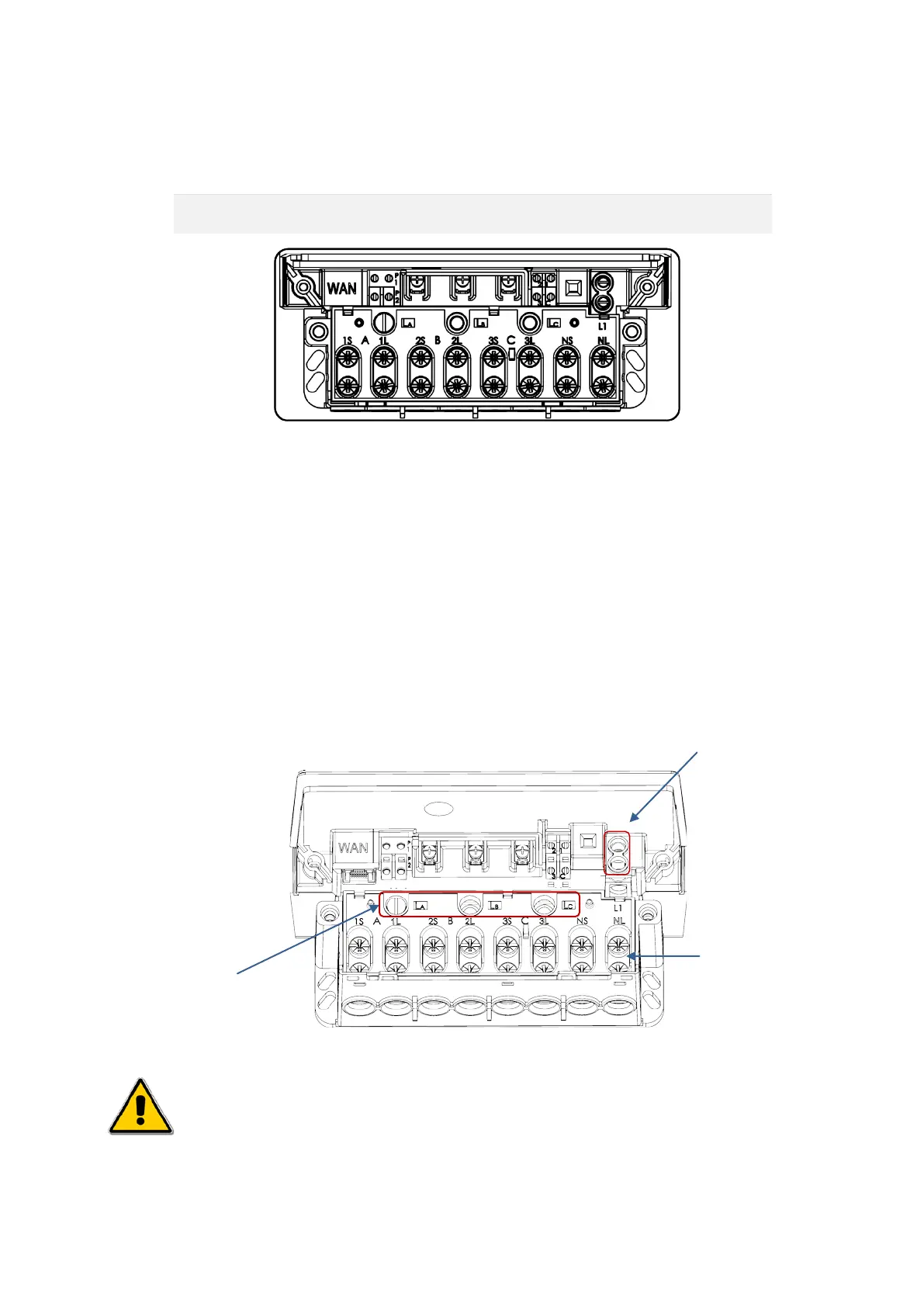
Figure 7: Terminal Block showing all the Load Terminals
2. For Load Control connections, do the following:
a.
Pull out the insulation cover provided for the phase selection sockets on the Sprint 211’s
terminal block. (Refer Figure 10: Load Control Connections). By default, the selection socket
LA is set to energise the auxiliary load connected to L1. To select supply from a different
phase, tighten the screw provided in any ONE of the phase selection sockets i.e. LA, LB or LC
above each phase.
b. Next insert the cable into the conductor shroud provided for terminal L1 and tighten the screws
corresponding to the terminals (positioned adjacent to each other.). Refer Figure 10: Load
Control Connections below.
c. Fix the phase selection cover back onto the sockets.
Figure 8: Load Control Connections (Line diagram)
Attention
Be extremely careful to ensure that no conductor part of the cable is in direct contact with any
other conductive surface.
selection
sockets
load
terminals
BGX701-160-R01
Sprint 211 Installation Manual Page 25 of 48