3 Active export, Reactive export, Lagging PF
4 Active import, Reactive export, Leading PF
8.
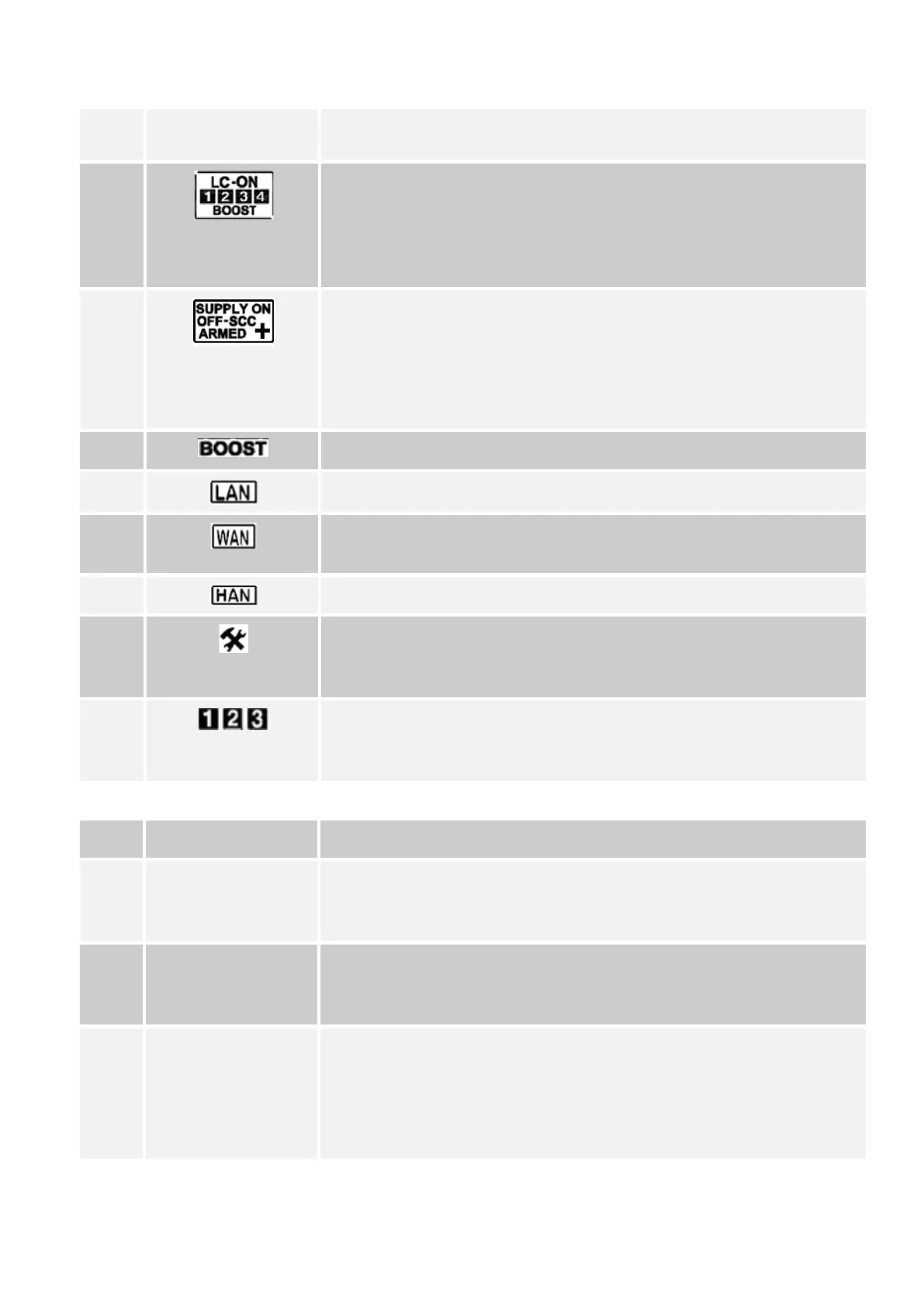
Load contactor annunciators - glowing of a particular LC annunciator
indicates that the switch state is ON. The annunciator is turned off when the
switch state is OFF. For Sprint 211, only auxiliary switch 1 is used. During
the switch time randomisation period, auxiliary switch 1 flashes to indicate
the connection status.
9.
Supply contactor annunciators - Indicates the current connection status of
the Supply Contactor. The Switch symbol is illuminated with ON / Armed /
OFF annunciators for connected / armed / disconnected status respectively.
Note:
SCC is not used.
10.
Boost indicator - This icon indicates activation of boost.
11.
NOT USED
12.
WAN communication indicator - Indicates presence of 3G/ GPRS
communication modules.
13.
Indicates that the meter is paired or ready for pairing with the HAN device
14.
Service status mode indicator - Indicates that attention and due service by
authorised personnel is needed for maintenance e.g. Real Time Clock
failure.
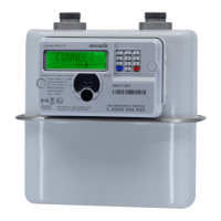
15.
Phase annunciators - Indicate the presence of supply voltages at the
respective phase. The annunciators also flash if reverse current is detected
in any of the phase.
Table 8: Operations possible through Sprint 211 push buttons
S. No. Function Details
1.
Parameter Navigation Sprint 211 may be configured to display a desired list of parameters. These
parameters are logically grouped to appear as a different display page, each
of which is assigned an individual display ID.
2.
Boost Activation Boost can be activated by holding the right push button pressed for five
seconds. The Boost annunciator glows when boost is activated. Similarly,
Boost can be deactivated by repeating this process.
3.
Metrological LED
configuration
The metrological LED can be configured to flash on desired energy channel
using the parameter navigation function.
Note: This is applicable only till midnight cross over, following which, it
switches to the factory configured settings. The same is applicable for a
power interruption.
Page 28 of 48 Sprint 211 Installation Manual BGX701-160-R01