MRD 5800 – User Manual
Page 22 (116)
shown in ORANGE are user configurable settings. Text shown in BLUE is not user
configurable and is strictly a status or value. To minimize the status windows again click
the icon.
Status in the MRD 5800 web interface is shown with LED status indicators:
Green LED
Status is good. No errors are present and function is operating
normally.
Red LED
Status indicates function is affected by active error. To view the
errors navigate to Alarms panel to view Active Errors.
Grey LED
Status is inactive. Function is currently disabled or unavailable.
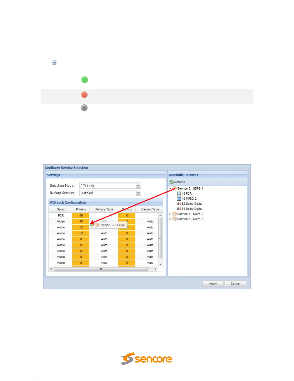
4.1.4 Drag and Drop Menus
Certain menus in the MRD 5800 allow the user to drag and drop items to auto populate
fields. Conditional Access and Service Selection menus are some examples of menus
that drag and drop can be used. In the example below a service in the transport stream
view on the right hand side of the window is selected and dragged over to auto populate
the PIDs in the service selection section.
4.2 Main Panel
The Main panel of the MRD 5800 web interface is used to configure the unit to decode,
de-encapsulate and demodulate. When configuring the MRD 5800 the user begins at the
top of the menu and works down. The inputs are configured, then descrambling (if
present), then service or PIDs are selected for decode, then outputs are configured.
Pictured below is a fully populated unit with all options licensed.
 Loading...