R301 RF POWER SUPPLY OPERATOR’S MANUAL
SERIAL COMMAND REFERENCE CHART
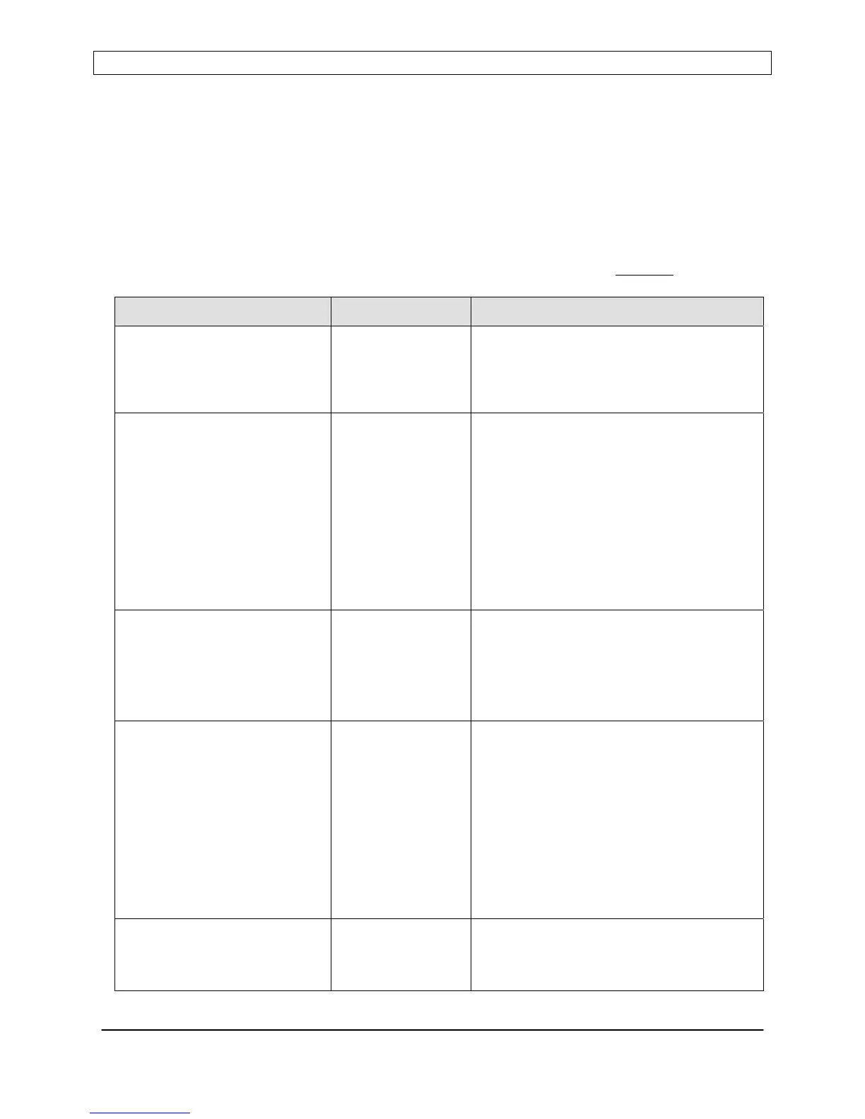
NOTES: The underscore character ( _ ) indicates a space
<crlf> indicates carriage return - line feed terminator
<cr> indicates carriage return terminator.
Prompt character is the greater-than (>) symbol
The letter “X” indicates a variable character.
Response to all invalid commands: “N<cr>”
Responses shown in the chart below assume ECHO mode is disabled
.
To Send Description/Comment
Query Status Q<cr> Returns status in the form of a mapped
string, terminated with <cr>. See Serial
Command details for string mapping
information.
Query the Control Voltage V?<cr> Returns the Control Voltage, with
scaling and probe attenuation factors
applied.
Response: -XXXX<cr>
(Negative polarity is assumed)
Note: Because the R301 only has one
(1) External FEEDBACK input, this
command is identical to the “0”
command.
Query Power Leveling Mode LVL?<cr> Returns the current power leveling
mode:
Response:
0<cr> for Forward Power Leveling
1<cr> for Load (net) Power Leveling.
Query the DC Bias Voltage 0?<cr> Returns the developed DC Bias Voltage,
with scaling and probe attenuation
factors applied.
Response: -XXXX<cr>
(Negative polarity is assumed)
Note: Because the R301 only has one
(1) External FEEDBACK input, this
command is identical to the “V”
command.
Assert SERIAL control
mode
***<cr> Sets the serial interface as the command
(control) source.
Response: <prompt> <cr>
Page 24
Seren IPS Inc.
6100130000 Rev. 0.05
 Loading...