R301 RF POWER SUPPLY OPERATOR’S MANUAL
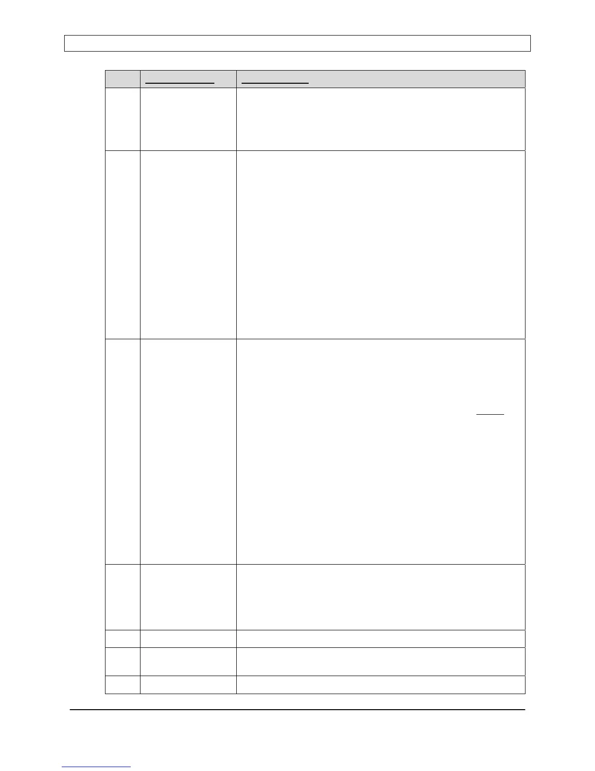
PIN
SIGNAL NAME DESCRIPTION
pre-position Seren IPS Inc. AT-Series Matching Networks.
Refer to “Matching Network Preset Mode”, “Tune Capacitor
Preset Position”, and “Load Capacitor Preset Position” in the
Programmable Parameters section.
Measure monitor voltage with respect to pin 23 (REFRET).
12 FEEDBACK External feedback voltage signal. Analog input, 0 to +10.0VDC .
Internally connected to pin 24.
Use pin 16, 17, 18, or 21 (GNDI) for return reference.
The RF Power Supply will automatically adjust its output power
to maintain the FEEDBACK signal’s magnitude at the same
level as the SETPOINT signal magnitude. The PROBE voltage
will be displayed on the front panel. The PROBE attenuation
factor can be configured from the front panel.
The external feedback signal is derived from a voltage probe
(RF or DC) located elsewhere in the plasma or process system.
Refer to the controls section for detailed instructions on how to
configure and use this mode.
Note: The feedback voltage polarity must match the setpoint
input’s (pin 13) polarity for proper operation of voltage control
mode.
13 SETPOINT Power or Voltage setpoint input. Analog, high-impedance,
differential input with selectable 0 to +5.0VDC or 0 to +10.0VDC
range via front panel controls.
Refer to the controls section of the operator’s manual for
detailed instructions on how to configure and use this mode
NOTE: Ground return (GNDI, pin 16,17,18, or 21) MUST
be
referenced to common or ground at the setpoint voltage source
(system controller) or the RF output power will behave
erratically.
In Power Control mode, sensitivity is 300 Watts at 5.0VDC
16.66mV per Watt) or 300 Watts at 10.0VDC (33.33mV per
Watt) depending on range selected.
NOTE: Feedback voltage range and polarity must match
setpoint voltage range and polarity for proper operation in
voltage control mode.
Pin 13 is the positive (+) input of the differential setpoint
amplifier.
Active only in ANALOG control mode.
14 MAINS INTLK 2 A contact closure between pin 1 and pin 14 is required to allow
AC mains power to engage. An open circuit between pin 1 and
pin 14 disables AC mains power. 24VAC current loop, 100 mA
maximum current
This signal is active in Panel, Analog, or Serial control modes
15 INTERLOCK-RTN Ground return for External Interlock (pin 2)
16 GNDI Ground return for pins 3,4,5,6,7,8,13,19. Internally connected to
chassis ground.
17 GNDI Ground return for pins 3,4,5,6,7,8,13,19. Internally connected to
Page 39
Seren IPS Inc.
6100130000 Rev. 0.05