R301 RF POWER SUPPLY OPERATOR’S MANUAL
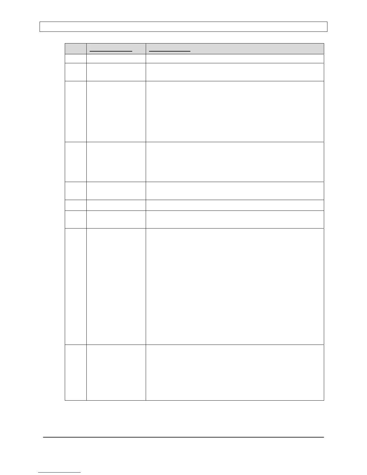
PIN
SIGNAL NAME DESCRIPTION
chassis ground.
18 GNDI Ground return for pins 3,4,5,6,7,8,13,19. Internally connected to
chassis ground.
19 RL-IN Remote Limit input. Analog input, 0 to +5VDC range. Use pin
16,17,18, or 21 (GNDI) for return reference.
Used in dual-bias or multiple power supply systems to fold-back
the power supply’s output power if reflected power is detected
by another power supply in the system. Output power folds
back in response to an external voltage applied to this input.
Foldback threshold is factory preset at +5.00VDC (Disabled).
Consult factory for assistance.
20 RL-OUT Remote Limit Output. Analog output, 0 to +10VDC range.
Buffered, high-speed, non-linearized directional coupler
reflected power signal. Return reference is pin 23.
Used on dual-bias or multiple power supply systems. Consult
factory for assistance.
21 GNDI Ground return for pins 3,4,5,6,7,8,13. Internally connected to
chassis ground.
22 FWDRET Forward Power Monitor return. Analog output. For pin 10.
23 REFRET Reflected Power Monitor/Remote Limit return. Analog output.
For pins 11 and 20.
24 FEEDBACK External feedback voltage signal. Analog input, 0 to +10.0VDC.
Internally connected to pin 12.
Use pin 16, 17, 18, or 21 (GNDI) for return reference.
The RF Power Supply will automatically adjust its output power
to maintain the FEEDBACK signal’s magnitude at the same
level as the SETPOINT signal magnitude. The PROBE voltage
will be displayed on the front panel. The PROBE attenuation
factor can be configured from the front panel.
The external feedback signal is derived from a voltage probe
(RF or DC) located elsewhere in the plasma or process system.
Refer to the controls section for detailed instructions on how to
configure and use this mode.
Note: The feedback voltage polarity must match the setpoint
input’s (pin 13) polarity for proper operation of voltage control
mode.
25 INVPROBE Inverted Probe Output. Analog output, 0 to +10.0VDC.
Inverted polarity signal derived from the rear panel “PROBE”
BNC connector. Magnitude of the signal remains identical,
polarity changed from negative (at the PROBE connector) to
positive.
Connect to pin 24 (if required) when using external feedback to
regulate RF output level.
Page 40
Seren IPS Inc.
6100130000 Rev. 0.05