SCORPIO 38’ - 45’ - PARTS AND COMPONENTS DESCRIPTION - Telescopic arm
Version 1.02 May 27, 2022
28
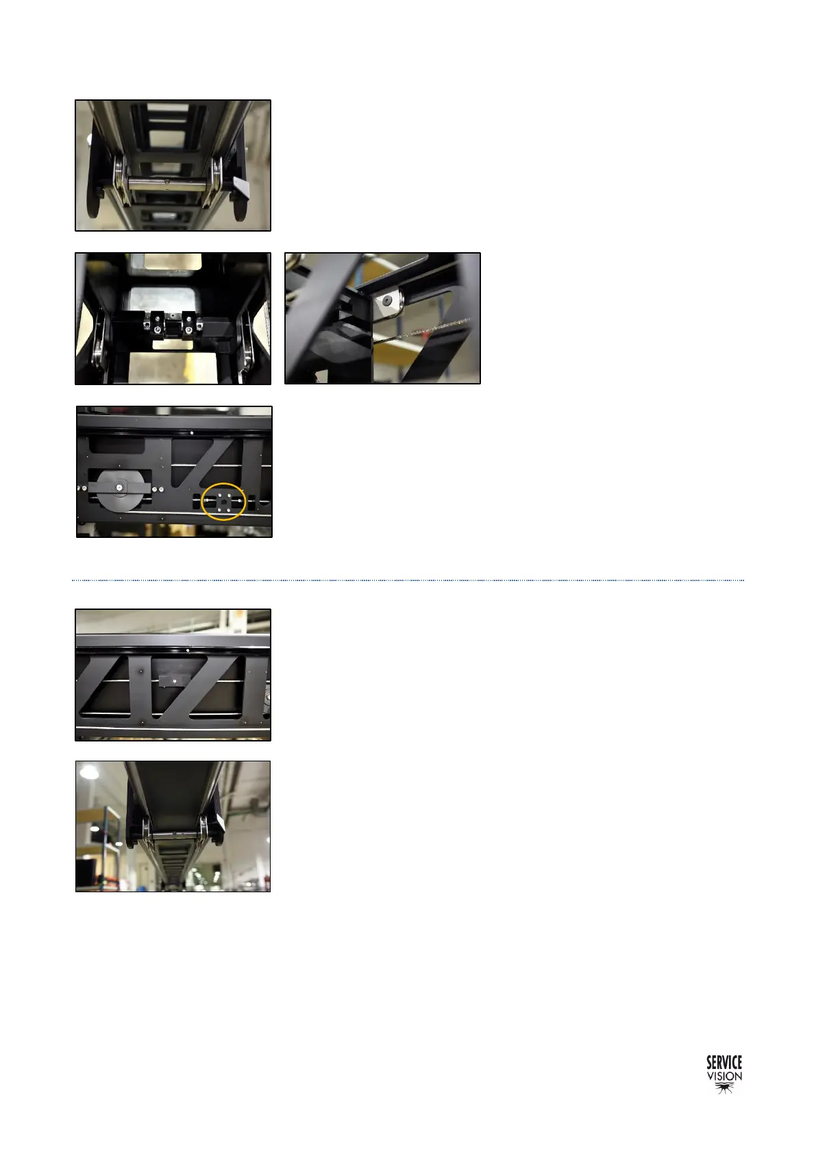
Using the same principle than the first section, the second section
supports in the 2 front metallic wheels in the flange from the first
section using the rails located underneath the second section. These
sets of wheels are mounted in an axis that is eccentric in the left side
and there is a mark indicating which is the highest eccentric point. By
losing this axis is possible to adjust the eccentric axis.
Inside the back part of the second
section there are 4 sets of metallic
wheels (2 sets in top and 2 sets in the
bottom) that runs along rails from the
first section and works exactly as the
ones in the first section.
As the first section, the second section has leaning pulleys to
transmit the movement to the third section (fig. 02.83-02.84). And as
the first or the main section it has guiding rubber wheels in the front
flange to prevent oscillating movements when there are sudden
movements.
2.4.2.3 THIRD SECTION
With the same mechanism as the second one, the third section is
attached to the first section (fig. 02.81-02.89) with a closed loop of
cables. When the leaning pulleys from the second section moves, the
loop of cables pulls from the link in the third section. To detach the
third section, remove this link and the section will be free.
As the previous sections, the third one is supported in 4 points: the
sets of metallic wheels from the previous section and the rear wheels
from top and bottom.
The difference between the third and the previous sections is the
kind of bottom rear wheels inside the section: the previous ones where
metallic sets of wheels sliding along rails and this one and the fourth
have rubber wheels inside in a vertical and horizontal position (fig.
02.91).
Since there are no rails, the lateral rubber wheels correct the lateral
movement of the section when it telescopes. The vertical wheels
correct the inclination of the section as the metallic ones in the previous
sections.