SCORPIO 38’ - 45’ - MAINTENANCE & SERVICE - Electronic Boards
Version 1.02 May 27, 2022
SERVICEVISION BIS SL
Ríos Rosas, 20 · 08940 CORNELLA DE LLOBREGAT (Barcelona) Spain · Tel. 34 93 223 86 30 · Fax 34 93 223 86 31 73
comercial@servicevision.es · www.servicevision.es
6.3 ELECTRONIC BOARDS
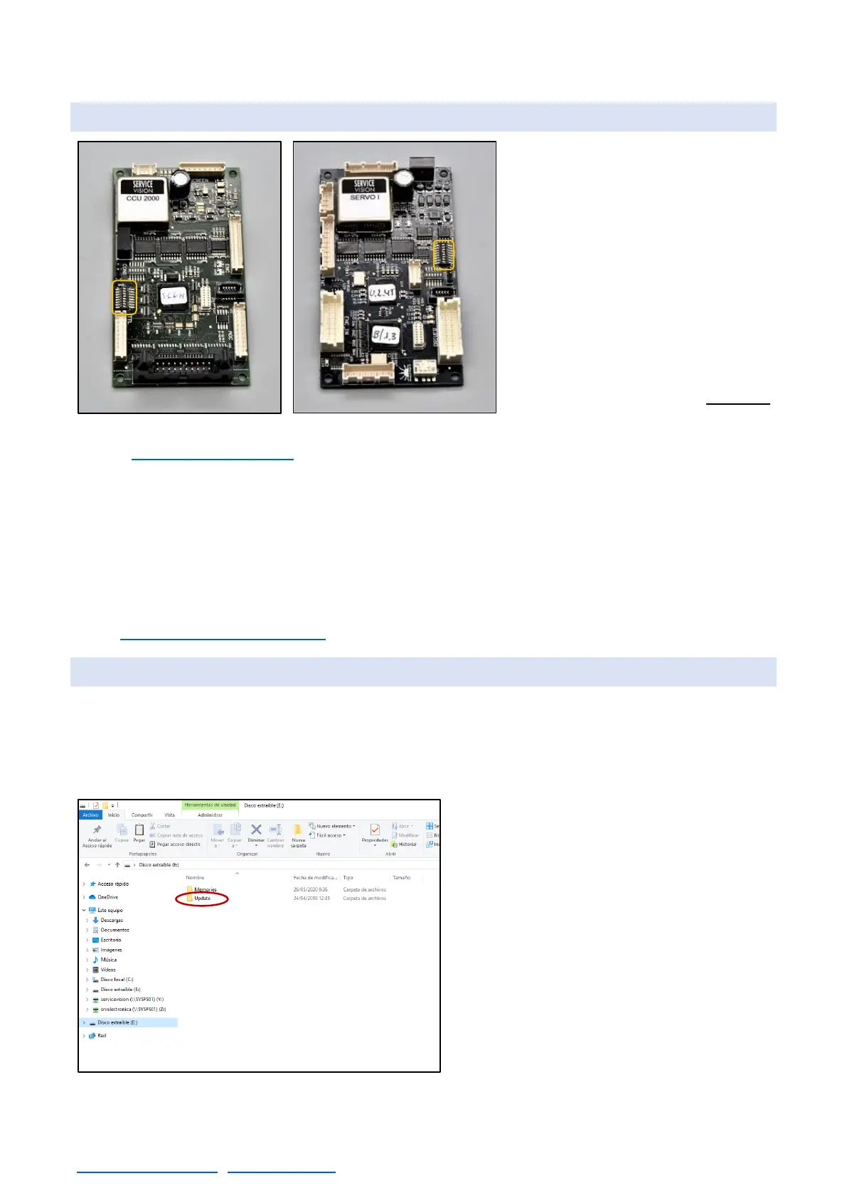
There are 2 kind of electronic boards
inside of the crane: the SERVO and
the CCU. They look very similar but
they make different functions. The
CCU controls the user interface and
the SERVO controls motors. To
replace them, remove all the
connectors from the board, unscrew
the plastic screws holding the board
and remove them from the system.
Notice that every board have a DIP
switch on it. Be sure to copy the DIP
switch of the board BEFORE
removing the damaged board.
In the chapter Documentation there is information of the possible DIP switch configurations for the
SERVO and the CCU. There is one SERVO inside the electronic box and one SERVO inside the
leveling head. There is only one CCU board placed inside the electronic box.
There are two driver boards inside the electronic box to control the motor of the arm and the motor
for the CWE/Column. There is another driver in the leveling head. To change any driver, remove the
screws holding the driver in place and then disconnect the connectors from the driver and connect
them exactly in the same pins on the new driver. The driver for the leveling head can be acceded by
removing the labeled cover from the leveling head. The drivers need to be adjusted for every motor.
In the chapter 6.5 Driver adjustment it is explained how to adjust them.
6.4 LOADING SOFTWARE TO THE SERVO/CCU
In the electronic box there is a slot for SD Cards. The SD Card reader is normally connected to the
CCU but there is one connector in the SERVOs also to connect the SD Card reader. To LOAD
software in the boards the software needs to be inside an SD Card. Servicevision will send to the
users a new software every time it is developed. This software will be a file called “XXXX.bin”.
Copy the software file (*.bin) inside the
UPDATE folder. The access path should be:
X:\UPDATE\*.bin. (X is the name of the SD
CARD in the computer).
Once the file is in the folder called update
(only one file in the folder), introduce the SD
card into the loader and connect it to the board
to be updated.