SCORPIO 38’ - 45’ - PARTS AND COMPONENTS DESCRIPTION - Telescopic arm
Version 1.02 May 27, 2022
SERVICEVISION BIS SL
Ríos Rosas, 20 · 08940 CORNELLA DE LLOBREGAT (Barcelona) Spain · Tel. 34 93 223 86 30 · Fax 34 93 223 86 31 27
comercial@servicevision.es · www.servicevision.es
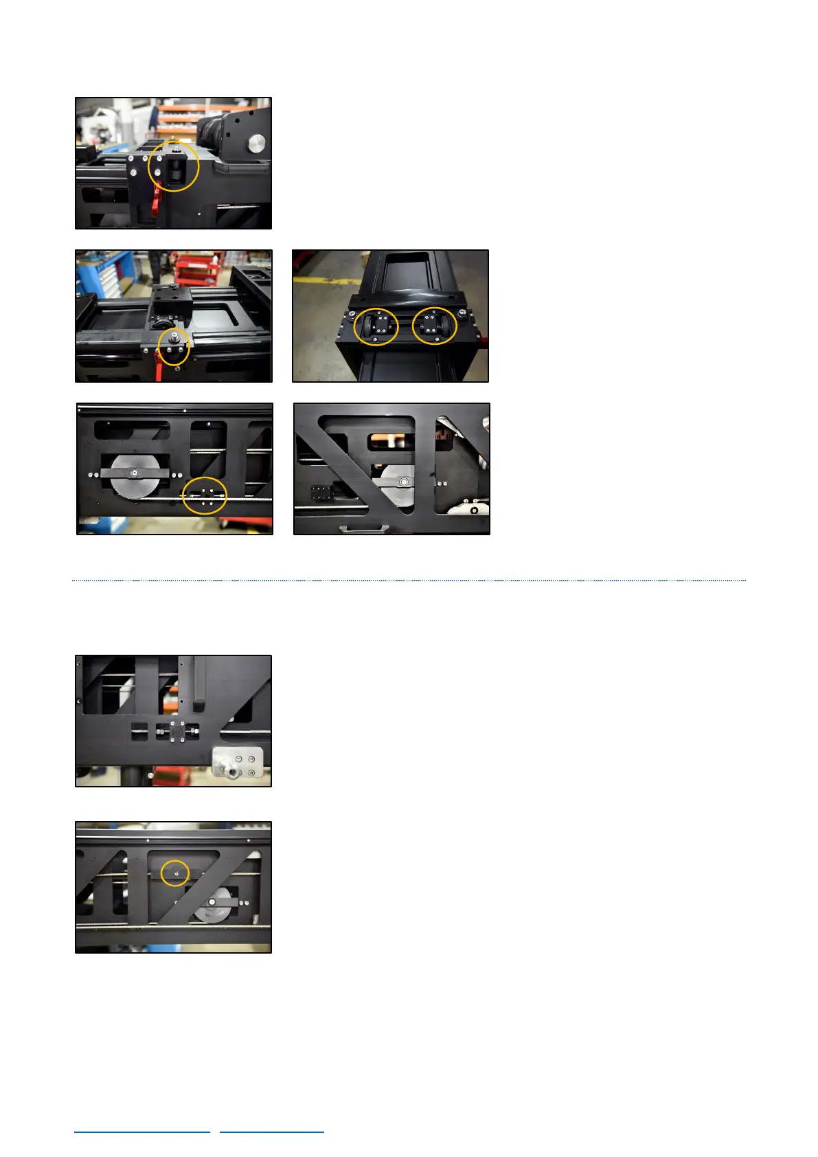
In the front flange of the main arm there are four rubber wheels (2
on top and one in each side) with the purpose of guide the first section
in case a sudden pan or tilt movement is made by the operator.
These sets of wheels are in every flange of the Main, First, Second
and Third section to guide each section in case a hard movement is
performed.
All these wheels are eccentric
and they can be adjusted by losing
the bracer of the top wheels and
moving the axis using the holes in it
to approach it or move them away
from the section. A proper adjust
for these wheels is as close as
possible but without touching the
next section.
In the first section there is also 4
leaning pulleys, 2 in front of the
section (one per side) and 2 in the
back (one per side). These pulleys
are part of the mechanism to move
the second section, the function is
detailed on the next chapter.
2.4.2.2 SECOND SECTION
The Second section is moved with a double cable system that links the Second section with the
Main section.
When the first section is pulled out, the leaning pulleys on it (fig.
02.81-02.82) move with it. The cables passing through those pulleys
are linked at both ends of each cable in the Main section and the
Second section (fig. 02.83-02.84). Since the Main section is fix, the
link from the second section pulls from this one in the direction of the
pulleys.
This link in both sides needs to be removed in case the user wants to
disassemble the second section from the arm. To do it, unscrew the
bolt and pull the link up. Once is detached, the movement of the
second section is no linked with the first section anymore and can be
slid using the 4 support points of the section: the 2 sets of metallic
wheels from the first section and the 2 sets of inside metallic wheels
from the second section.