SCORPIO 38’ - 45’ - PARTS AND COMPONENTS DESCRIPTION - Telescopic arm
Version 1.02 May 27, 2022
26
2.4.2 TELESCOPIC SECTIONS
The telescopic crane is made up of four telescopic aluminum tubes. Each one of them is supported
in the section before it by a system of guide wheels and rails. To move each section there is a cable
system that links each section with the second before it.
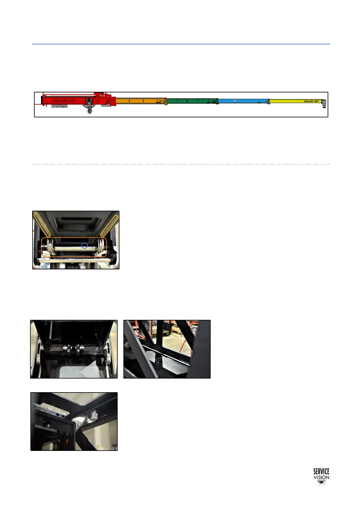
In the drawing, the red one is the main section which has been described in the previous chapter.
The orange one is called the First section and is the only one linked to the motor. The name of the
rest of the sections are Second section (green), Third section (blue) and Fourth section (yellow).
2.4.2.1 FIRST SECTION
The first section is the first one to move when the motor moves. The movement of any other
component of the crane is somehow linked to this section. The system used to move this section has
been explained in the previous chapter.
The First section has 2 rails underneath along the whole section that
are supported on 2 sets of metallic wheels from the front flange of the
Main arm. These sets of wheels are mounted in an axis that is
eccentric in the left side and there is a mark indicating which is the
highest eccentric point. By losing this axis is possible to adjust the
eccentric axis.
Inside the main section, there are 2 rails in the bottom to support the
rear wheels from the first section. The rear wheels in the first section
are metallic and eccentric. This sets of wheels can be adjusted
independently by losing the flange that holds each axis with the 2
screws, and then move the axis using the holes in it.
The rear sets of wheels need to be
adjusted with the crane completely
extended. If the crane is fully
extended, the pressure of these
wheels is released and passed to the
top rear wheels (fig. 02.77).
The top sets of metallic wheels run along 2 sets of rails and cannot
be adjusted. These wheels ensure that, when the crane telescopes
out and is heavier in the front part, is still straight and aligned. These
wheels set the position for the eccentric of the rear bottom wheels.
With the proper adjustment of all these wheels the section is always
supported in 4 points at least.