SCORPIO 38’ - 45’ - PARTS AND COMPONENTS DESCRIPTION - Telescopic arm
Version 1.02 May 27, 2022
SERVICEVISION BIS SL
Ríos Rosas, 20 · 08940 CORNELLA DE LLOBREGAT (Barcelona) Spain · Tel. 34 93 223 86 30 · Fax 34 93 223 86 31 25
comercial@servicevision.es · www.servicevision.es
2.4.1.4 PROTECTION BARS
The protection bars mark the area of movement of the Telescopic counterweights, therefore NEVER
get in between the protection bars and the crane, there is a high risk of squashing if the crane moves.
These bars are also the support for the upper or lower operation bars to control the crane.
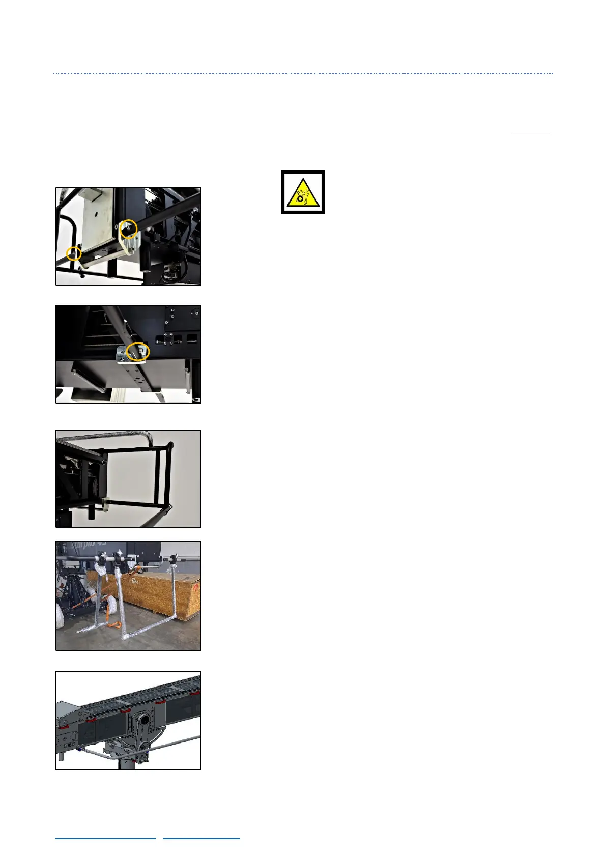
There are 2 pivots in both sides of the main arm, these pivots are used
for fixing the Protection bars to the crane. In these pivots is where the
screw that holds the side Protection bars are screwed (DIN912
M10x50mm).
In the frontal part of the protection bars (fig. 02.69) there are holes in
the protection bars. These holes can be used to pass power, video or
different cable lines to a monitor for the crane operator. The exit hole
for that monitor is in the middle of the protection bar.
The upper operation bars are used for when the crane is tilted up, in
order to control the movements of the crane in this position. They also
give rigidity to the protection bars and the portable display of the
electronic box can be mounted on them with the proper bracket. The
upper structure is attached with 8 screws (DIN912 M10x35mm).
The Hand Command can be hold into the bracket in the side protection
bar.
There are two kind of lower operation bars: Single or Double. Both
of them are attached in the rear part of the side protection bars and
they are used to control the crane when is tilted down or when the
column is too high to be operated from the side bars.
The last remarkable part of the main arm are the cable holders.
These holders are used to pass the cables to the electronic box, the
leveling head or the remote head safely strapped on them.
To dismount them, open the side cover of the holder and there will
be access to the screw of it. It may be necessary in order to pass some
cables with big connectors.