SCORPIO 38’ - 45’ - PARTS AND COMPONENTS DESCRIPTION - Telescopic arm
Version 1.02 May 27, 2022
SERVICEVISION BIS SL
Ríos Rosas, 20 · 08940 CORNELLA DE LLOBREGAT (Barcelona) Spain · Tel. 34 93 223 86 30 · Fax 34 93 223 86 31 29
comercial@servicevision.es · www.servicevision.es
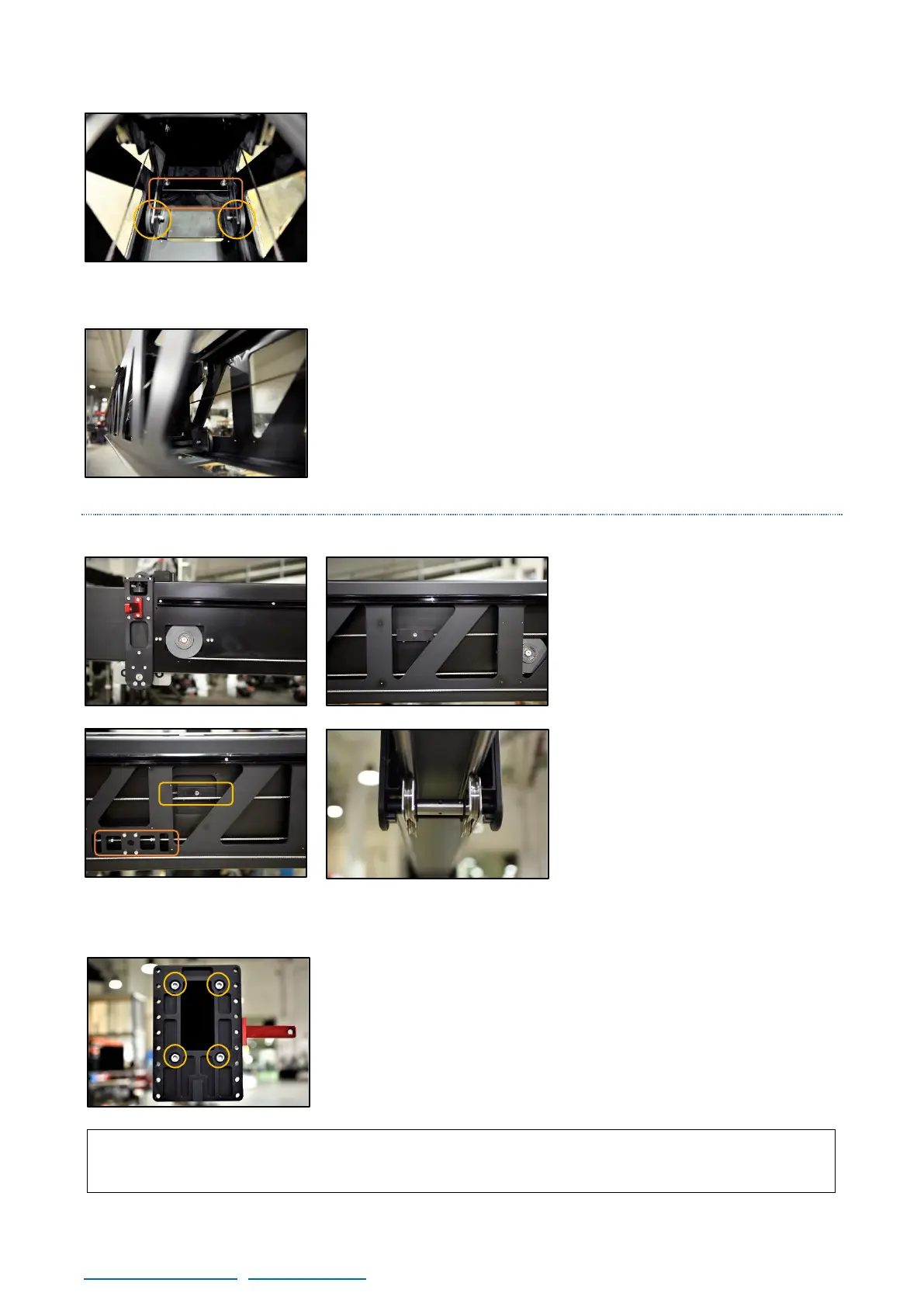
To adjust these wheels is needed a special tool to move the
eccentric axis to the proper position.
The rear top wheels are metallic and are the ones that mark the
proper position of the rear rubber wheels: when the crane is fully
extended and the weight of the section supports in these wheels, all
the bottom rubber wheels need to be touching the second section.
This is the last section with leaned pulleys. They connect the
second section with the fourth one. It is also the last with the front
flange with the top guiding wheels.
2.4.2.4 FOURTH SECTION
The fourth section is the last section
linked. To have access to this link
there is only one position (fig. 02.95)
and the system is the same as the
previous sections: the pulleys from
the previous section move and pulls
this section with it. To detach the
movement from this section, remove
the link from it.
It is supported in the third section
front wheels and this set of wheels is
eccentric as the ones in the other
sections. The rear wheels from this
section cannot be adjusted outside
the factory because there is no room
to access to them. The system of the
rear wheels for this section is the
same used on the third one.
In the end of the section there is the Leveling Head Fastening Plate.
It is hold with four bolts and if the screws are loose, there is a slight
play side to side to finish adjusting the lateral level at the end of the
crane. This adjustment needs to be done with the base leveled and
checked with the crane completely closed and open to verify that the
eccentric wheels from the previous sections are properly adjusted.